2 specification – Comtech EF Data SNM-1001 User Manual
Page 45
Theory of Operation
SNM-1001 Network Control Modem
4–14
Rev. 1
The Request To Send (RTS) lines are hardwired by JP11 to the Clear To Send (CTS)
lines on the Demod/M&C card (AS/4973-2) for Continuous mode operation.
The RTS line is activated for Burst mode by jumping pins 1 and 2 on JP11.
Data Mode (DM) indicates that the modem is powered up.
Receiver Ready (RR) indicates that an RF carrier is being received and demodulated
with a sufficiently low error rate for the decoder to remain locked.
The EIA-422/449 interface also provides bi-directional relay loopback of both the clock
and data at the DCE interface.
•
In loopback from the DTE side, SD is connected to RD, and either ST or TT
(in Internal or External mode) is looped back to RT.
•
From the modem side, the received data and recovered clock are routed back to
the modulator input for retransmission.
The Common Equipment, Modulator, and Demodulator fault outputs are provided on dry
contact FORM C relays. They are available on the Fault connector on the modem rear
panel.
Fault indicators are also provided on Transistor/Transistor Logic (TTL) open collector
drivers on the EIA-422/449 connector.
•
The TTL MOD fault indicates a Modulator or Common Equipment fault.
•
The TTL DEMOD fault indicates a Demodulator or Common Equipment fault.
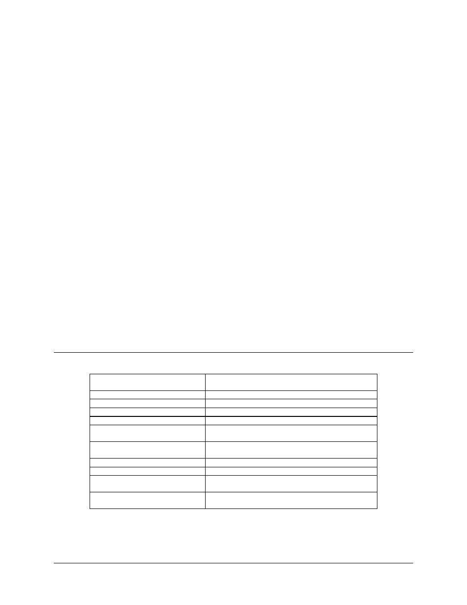
4.4.1.2 Specification
Circuit Supported
SD, ST, TT, RD, RT, DM, RR, MC, MOD FAULT,
DEMOD FAULT.
Amplitude (RD, RT, ST, DM, RR)
4,
±
2V differential into 100
Ω
.
DC Offset (RD, RT, ST, DM, RR)
0.0,
±
0.4V.
Impedance (RD, RT, ST, DM, RR)
Less than 100
Ω
, differential.
Impedance (SD, TT, MC)
100,
±
20
Ω
, differential.
Polarity
True when B positive with respect to A.
False when A positive with respect to B.
Phasing (RD, RT)
False-to-true transition of RT nominally in center of RD data
bit.
Symmetry (ST, TT, RT)
50
%,
±
5
%
.
Frequency Stability (ST)
±
100 PPM.
Modulator Fault
Open collector output. Fault is open circuit.
15V maximum, 20 mA maximum current sink.
Demodulator Fault
Open collector output. Fault is open circuit.
15V maximum, 20 mA maximum current sink.