Comtech EF Data SNM-1001 User Manual
Page 39
Theory of Operation
SNM-1001 Network Control Modem
4–8
Rev. 1
MICRO-
COMPUTER
BUS
MICROCOMPUTER
INTERFACE
VITERBI DECODER INCLUDES
CHANNEL BER DETECTION
DESCRAMBLER
LOCK
DETECT
RECEIVE
AMBIGUITY
RESOLVER AND
VW DETECTOR
INPUT
BUFFER
RECEIVE
CLOCK
AGC
CONTROL
COSTAS
PROCESSOR
I CHANNEL
Q CHANNEL
FREQUENCY
LOCKED LOOP
DDS
IF
CLOCK
RECOVERY
DEPUNCTURE
DECODER
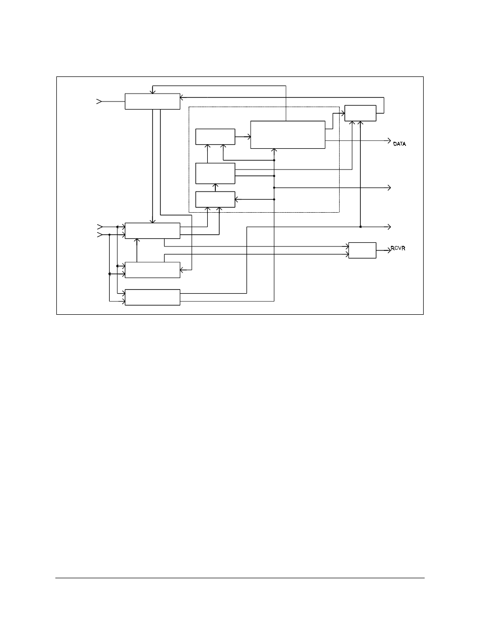
Figure 4-3. Viterbi Decoder Block Diagram
The Viterbi decoder processes 3-bit quantized R0 and R1 parallel code bits (symbols)
from the demodulator. The quantization is 3-bit soft-decision in sign/magnitude format.
This is a representation of the data transmitted, corrupted by additive white Gaussian
noise. The decoder uses the code symbols produced by the encoder to determine which
symbols have been corrupted by the transmission channel. The decoder corrects as many
corrupted symbols as possible.
The data signal passes through an ambiguity resolver, which compensates for the
potential 90° phase ambiguity inherent in a QPSK demodulator.
A set of branch metric values is then computed for each of the received symbol pairs.
The values are related to the probability that the received symbol pair was actually
transmitted as one of the four possible symbol pairs. The branch metrics are then
processed by the Add-Select-Compare (ASC) computer.
The ASC computer makes decisions about the most probable transmitted symbol stream
by processing the current branch metrics with the state metrics computed for the 64
previous decoder inputs. The results of the ASC computer are stored in memory called
“path memory.”