Maintenance testing, Test point samples, Aintenance – Comtech EF Data UT-4500 Series User Manual
Page 104: Esting
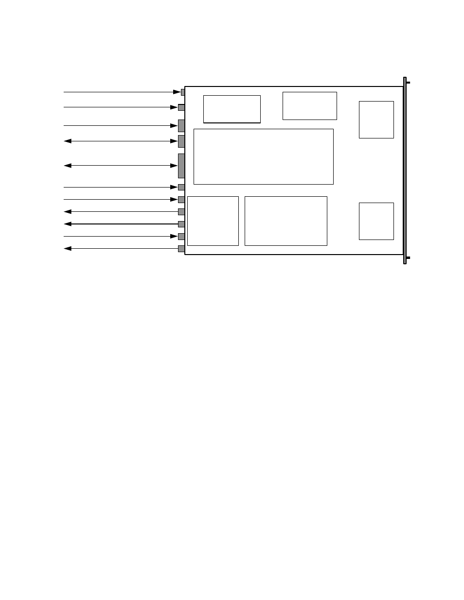
UT4500 Series Up Converter
MN/UT4500.IOM
Maintenance and Troubleshooting
Revision 2
86
Power
Supply
Reference
Oscillator
Fine
Step
Module
Sum
Loop
Module
Monitor & Control Assembly
RF Converter
Prime Power Cord Input
5/10 MHz Ref. Osc. Input
J2
P1
J1
J3
J4
J5
J7
J9
Summary Fault Relay Output
Serial Comm. Interface
(RS-485 / RS-232C)- COM 1
High Speed Bus (HSB)
IF Input (IF)
J6
J8
RF Loop Input (LP IN)
RF Loop Output (LP OUT)
RF Output (RF)
Transmit
I/O Switch
Module
(TSM)
IF Loop Input (LP IN)
IF Loop Output (LP OUT)
Figure 35. Converter Signal and Interconnecting Cable Diagram
(with TSM Switching Module).
7.2 M
AINTENANCE
T
ESTING
Use the instructions in Chapter 2, Installation, for installing the converter for checkout,
and the procedures in Chapter 3, System Operation, for operating the converter.
The converter is a Up Converter which translates the input IF frequency from 52 to 88
MHz (or optional 104 to 176 MHz) to an output RF frequency - for example, the RF
output frequency of the Model UT-4514 is 14000 to 14500 MHz. The IF input level is -
35 dBm (typical), and the RF output level is +10 dBm at 1 dB compression.
7.2.1 T
EST
P
OINT
S
AMPLES
The IF input and RF output can be monitored at the RF Sample Test Points on the front
panel. A BNC connector is provided for the IF sample, and an SMA connector is
provided for the RF output. The RF sample output level is -20 dBc nominal, and the IF
sample input level is -20 dBc nominal.