Physical configuration – Comtech EF Data UT-4500 Series User Manual
Page 33
Advertising
UT4500 Series Up Converter
MN/UT4500.IOM
Introduction
Revision 2
15
1.4 P
HYSICAL
C
ONFIGURATION
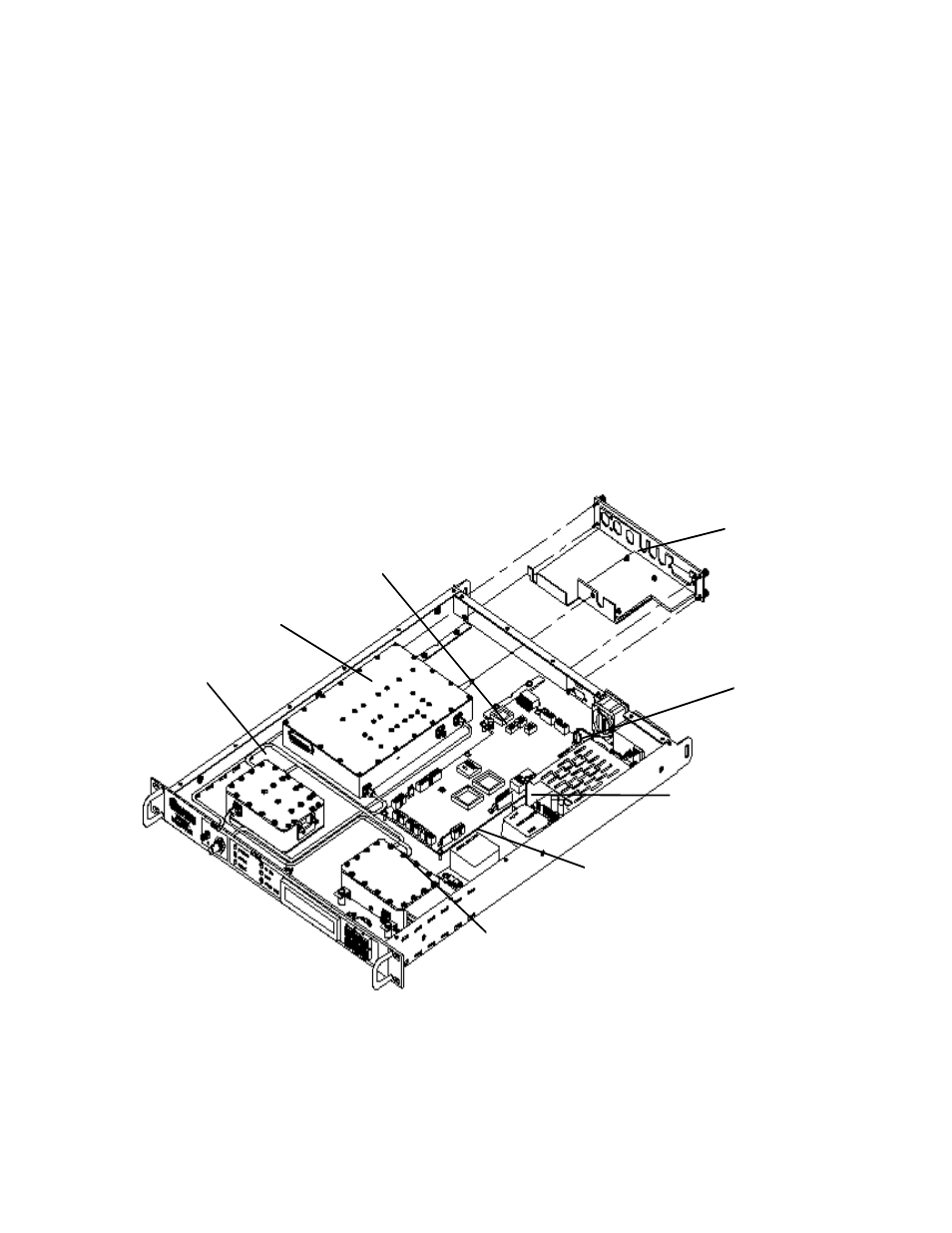
Figure 5 is a top view layout of a UT-4500 Series Up Converter chassis with the cover
removed. Major chassis components are shown in Figure 5. The major module
assemblies shown in the layout are:
Signal Path Module.
Step Loop Module.
Monitor & Control (M&C) Assembly.
Transmit I/O Switch Module - not shown - located in the right front space when
facing the rear of the chassis.
Reference Oscillator Assembly.
Sum Loop Module
Power Supply Assembly
Power Supply
Switch
Module
Filter
Module
Reference
Oscillator
Step
Module
Sum Module
Signal
Path
Monitor
& Control
Board
Figure 5. Physical Configuration - Up Converter
Advertising