2 part assemblies, 3 foundation, 1 protection of openings and threads – Flowserve Mark 3 User Manual
Page 13: 2 rigid baseplates - overview, 3 stilt and spring mounted baseplates, 1 stilt mounted baseplate assembly instructions
USER INSTRUCTIONS MARK 3 High Silicon Iron ENGLISH 71569249 09-04
4.2 Part assemblies
The supply of motors and baseplates are optional.
As a result, it is the responsibility of the installer to
ensure that the motor is assembled to the pump and
aligned as detailed in section 4.5 and 4.8.
4.3 Foundation
4.3.1 Protection of openings and threads
When the pump is shipped, all threads and all
openings are covered. This protection/covering
should not be removed until installation. If, for any
reason, the pump is removed from service, this
protection should be reinstalled.
4.3.2 Rigid baseplates - overview
The function of a baseplate is to provide a rigid
foundation under a pump and its driver that maintains
alignment between the two. Baseplates may be
generally classified into two types:
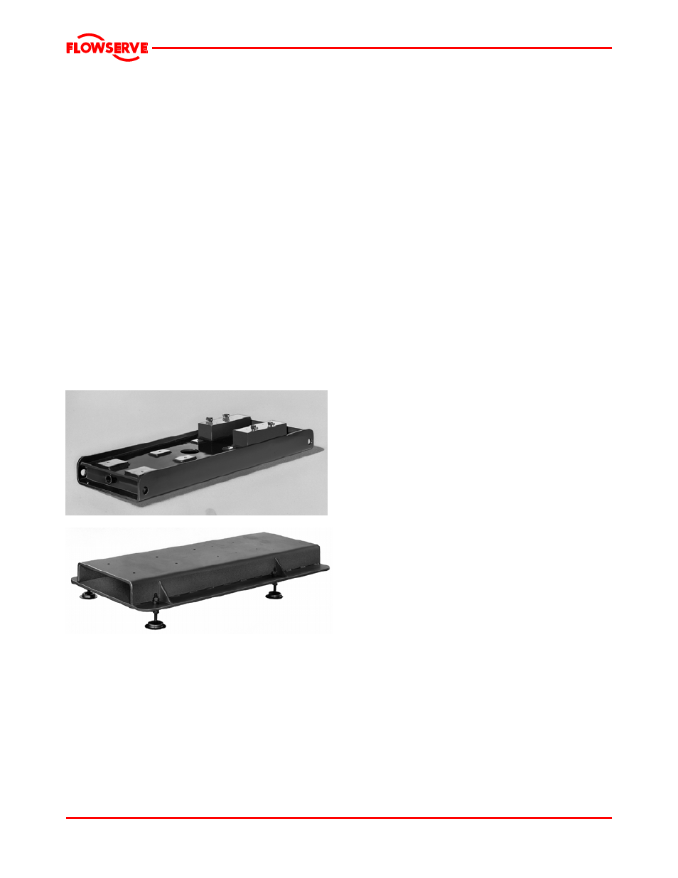
• Foundation-mounted, grouted design. (Figure 4-1.)
• Stilt mounted, or free standing. (Figure 4-2.)
Figure 4-1
Figure 4-2
Baseplates intended for grouted installation are
designed to use the grout as a stiffening member.
Stilt mounted baseplates, on the other hand, are
designed to provide their own rigidity. Therefore the
designs of the two baseplates are usually different.
Regardless of the type of baseplate used, it must
provide certain functions that ensure a reliable
installation. Three of these requirements are:
1. The baseplate must provide sufficient rigidity to
assure the assembly can be transported and
installed, given reasonable care in handling,
without damage. It must also be rigid enough
when properly installed to resist operating loads.
2. The baseplate must provide a reasonably flat
mounting surface for the pump and driver.
Uneven surfaces will result in a soft-foot condition
that may make alignment difficult or impossible.
Experience indicates that a baseplate with a top
surface flatness of 1.25 mm/m (0.015 in./ft)
across the diagonal corners of the baseplate
provides such a mounting surface. Therefore,
this is the tolerance to which we supply our
standard baseplate. Some users may desire an
even flatter surface, which can facilitate
installation and alignment. Flowserve will supply
flatter baseplates upon request at extra cost. For
example, mounting surface flatness of 0.17
mm/m (0.002 in./ft) is offered on the Flowserve
Type E “Ten Point” baseplate shown in figure 4-1.
3. The baseplate must be designed to allow the
user to final field align the pump and driver to
within their own particular standards and to
compensate for any pump or driver movement
that occurred during handling. Normal industry
practice is to achieve final alignment by moving
the motor to match the pump. Flowserve practice
is to confirm in our shop that the pump assembly
can be accurately aligned. Before shipment, the
factory verifies that there is enough horizontal
movement capability at the motor to obtain a
“perfect” final alignment when the installer puts
the baseplate assembly into its original, top
leveled, unstressed condition.
4.3.3 Stilt and spring mounted baseplates
Flowserve offers stilt and spring mounted baseplates.
(See figure 4-2 for stilt mounted option.) The low
vibration levels of Mark 3 pumps allow the use of
these baseplates - provided they are of a rigid design.
The baseplate is set on a flat surface with no tie down
bolts or other means of anchoring it to the floor.
General instructions for assembling these baseplates
are given below. For dimensional information, please
refer to the appropriate Flowserve “Sales print.”
4.3.3.1 Stilt mounted baseplate assembly
instructions
Refer to figure 4-3.
a)
Raise or block up baseplate/pump above the
floor to allow for the assembly of the stilts.
b)
Predetermine or measure the approximate
desired height for the baseplate above the floor.
c)
Set the bottom nuts [2] above the stilt bolt head
[1] to the desired height.
d)
Assemble lock washer [3] down over the stilt bolt.
Page 13 of 48