7 disassembly, 1 pump removal, 2 pump disassembly – Flowserve Mark 3 User Manual
Page 30
USER INSTRUCTIONS MARK 3 High Silicon Iron ENGLISH 71569249 09-04
6.7 Disassembly
6.7.1 Pump removal
a) Before performing any maintenance, disconnect the
driver from its power supply and lock it off line.
Lock out power to driver to prevent
personal injury.
b) Close the discharge and suction valves, and
drain all liquid from the pump.
c) Close all valves on auxiliary equipment and
piping, then disconnect all auxiliary piping.
d) Decontaminate the pump as necessary.
If Flowserve Mark 3 pumps
contain dangerous chemicals, it is important to
follow plant safety guidelines to avoid personal
injury or death.
e) Remove the coupling guard. (See section 5.5.)
f) Remove the spacer from the coupling.
g) Remove the suction and discharge flange bolting.
Exercise extreme care as the pump
casing will contain process fluid. Residual process
fluid should be neutralized or drained as allowed
by plant procedures.
h) Remove the fasteners holding the bearing
housing foot and adapter feet to the baseplate.
i)
Move the assembly away from the piping. Discard
the flange gaskets.
The pump assembly is heavy. It is
important to follow plant safety guidelines when
lifting it.
j)
Transport the assembly to the maintenance shop.
6.7.2 Pump Disassembly
k) Remove the coupling hub from the pump shaft
[2100].
l)
Remove casing nuts [6580.1] from bolts [6570.1].
Removing the clamping ring [1240] and suction
cover [1223]. Discard the cover gasket [4590.1].
m) Using the shaft key [6700], mount the impeller
wrench from the Flowserve Mark 3 tool kit (figure
6-1) to the end of the shaft. With the wrench
handle pointing to the left when viewed from the
impeller end, grasp the impeller [2200] firmly with
both hands (wear heavy gloves). By turning the
impeller in the clockwise direction move the
wrench handle to the 11 o’clock position and then
spin the impeller quickly in a counter-clockwise
direction so that the wrench makes a sudden
impact with a hard surface on the bench. After
several sharp raps, the impeller should be free.
Unscrew the impeller and remove from the shaft.
Discard the impeller gasket [4590].
Do not apply heat to the
impeller. If liquid is entrapped in the hub, an
explosion could occur.
The casing [1100] is not directly
attached to the power end. It is only held in
place by the impeller and seal. Support the
casing until removal is required.
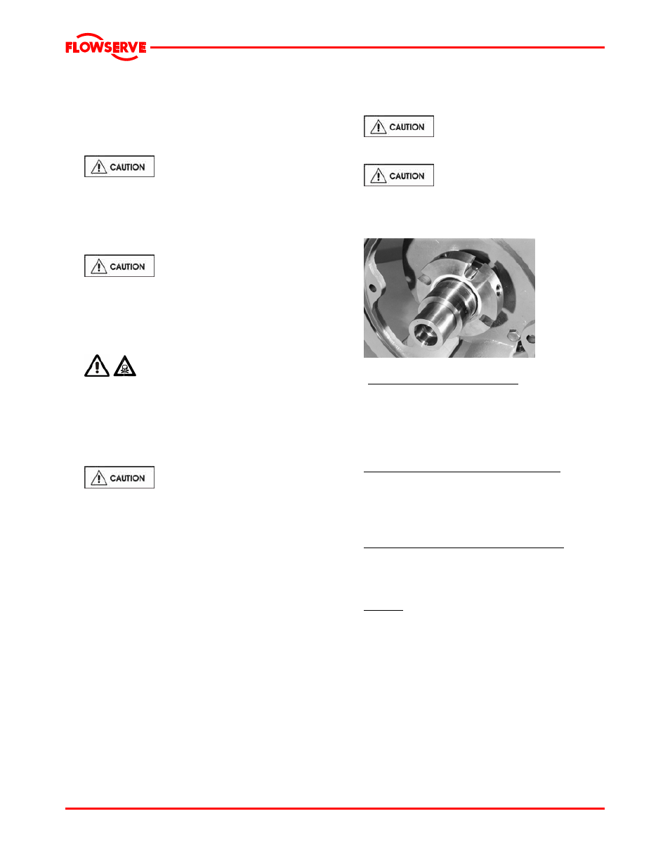
Figure 6-7
n)
Remove the seal or packing gland nuts [6580.2]
o)
Cartridge type mechanical seal [4200]
(figure 6-7), The spacing clips or tabs should be
installed prior to loosening the set screws which
attaches the seal to the shaft or removing it from
the casing seal chamber. This will ensure that
the proper seal compression is maintained.
p) Remove the casing seal chamber [1100].
q) Component type inside mechanical seal [4200]
Loosen the set screws on the rotating unit and
remove it from the shaft (see figure 6-8). Then
pull the gland [4120] and stationary seat off the
shaft. Remove the stationary seat from the
gland.
Component type outside mechanical seal [4200]
Remove the gland and the stationary seat.
Remove the stationary seat from the gland.
Loosen the set screws in the rotating unit and
remove it from the shaft.
Packing [4130] Remove it and the seal cage
[lantern ring, 4134]. Remove the gland [4120].
r) Discard all O-rings, gaskets and packing.
s) If the pump has a hook type sleeve [2400] it can
now be removed. Unit now appears as shown in
figure 6-9.
t) If the power end is oil lubricated, remove the
drain plug [6469] and drain the oil from the
bearing housing [3200].
Page 30 of 48