7 installed pump, 9 assembly of pump and seal – Flowserve Mark 3 User Manual
Page 35
USER INSTRUCTIONS MARK 3 High Silicon Iron ENGLISH 71569249 09-04
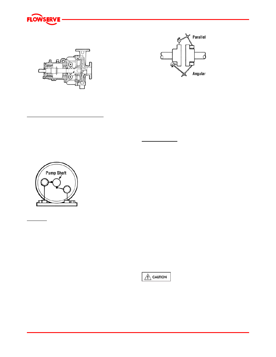
concentricity should be less than 0.13 mm (0.005 in.).
The diagram below shows how to measure this
concentricity.
Alignment
Concentricity
Many companies today are using laser alignment
which is a more sophisticated and accurate
technique. With this method a laser and sensor
measure misalignment. This is fed to a computer
with a graphic display that shows the required
adjustment for each of the motor feet.
6.8.4.7 Installed pump
Complete pump installed.
Shaft movement caused by pipe strain
Pipe strain is any force put on the pump casing by the
piping. Pipe strain should be measured as shown
below. Install the indicators as shown before
attaching the piping to the pump. The suction and
discharge flanges should now be bolted to the piping
separately while continuously observing the
indicators. Indicator movement should not exceed
0.05 mm (0.002 in.).
See section 4.8 for recommended final shaft
alignment limits.
Vibration analysis
Vibration analysis is a type of condition monitoring
where a pump’s vibration “signature” is monitored on
a regular, periodic basis. The primary goal of
vibration analysis is extension on MTBPM. By using
this tool Flowserve can often determine not only the
existence of a problem before it becomes serious, but
also the root cause and possible solution.
Pipe strain movement
Modern vibration analysis equipment not only detects
if a vibration problem exists, but can also suggest the
cause of the problem. On a centrifugal pump, these
causes can include the following: unbalance,
misalignment, defective bearings, resonance,
hydraulic forces, cavitation and recirculation. Once
identified, the problem can be corrected, leading to
increased MTBPM for the pump.
Alignment
Misalignment of the pump and motor shafts can
cause the following problems:
Flowserve does not make vibration analysis
equipment, however Flowserve strongly urges
customers to work with an equipment supplier or
consultant to establish an on-going vibration analysis
program. See note 3 under figure 6-19 regarding
acceptance criteria.
• Failure of the mechanical seal
• Failure of the motor and/or pump bearings
• Failure of the coupling
• Excessive
vibration/noise
The schematics below show the technique for a
typical rim and face alignment using a dial indicator.
It is important that this alignment be done after the
flanges are loaded, and at typical operating
temperatures. If proper alignment cannot be
maintained a C-flange motor adapter and/or
stilt/spring mounting should be considered.
6.9 Assembly of pump and seal
It is important that all pipe threads be
sealed properly. PTFE tape provides a very reliable
seal over a wide range of fluids, but it has a serious
shortcoming if not installed properly. If, during
application to the threads, the tape is wrapped over the
end of the male thread, strings of the tape will be formed
when threaded into the female fitting. These strings can
then tear away and lodge in the piping system.
Page 35 of 48