2 suction piping, 3 discharge piping, 5 pump and shaft alignment check – Flowserve Mark 3 User Manual
Page 17: 6 auxiliary piping
USER INSTRUCTIONS MARK 3 High Silicon Iron ENGLISH 71569249 09-04
equal to the fastener diameter but that do not bottom
out in the tapped holes before the joint is tight.
4.6.2 Suction piping
To avoid NPSH and suction problems, suction piping
must be at least as large as the pump suction
connection. Never use pipe or fittings on the suction
that are smaller in diameter than the pump suction size.
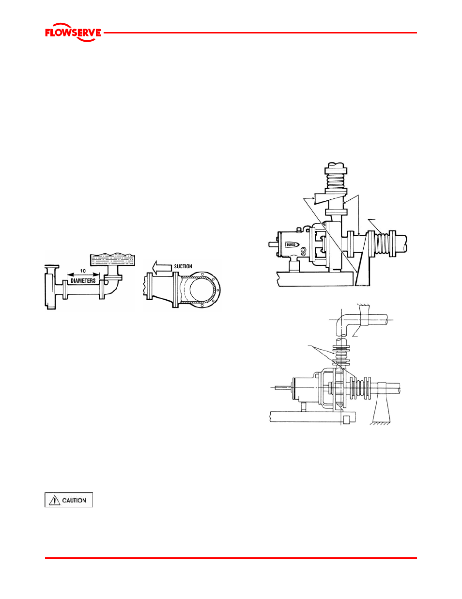
Figure 4-9 illustrates the ideal piping configuration with a
minimum of 10 pipe diameters between the source and
the pump suction. In most cases, horizontal reducers
should be eccentric and mounted with the flat side up as
shown in figure 4-10 with a maximum of one pipe size
reduction. Never mount eccentric reducers with the flat
side down. Horizontally mounted concentric reducers
should not be used if there is any possibility of entrained
air in the process fluid. Vertically mounted concentric
reducers are acceptable. In applications where the fluid
is completely de-aerated and free of any vapor or
suspended solids, concentric reducers are preferable to
eccentric reducers.
Figure 4-7 Figure 4-8
Avoid the use of throttling valves and strainers in the
suction line. Start up strainers must be removed shortly
before start up. When the pump is installed below the
source of supply, a valve should be installed in the
suction line to isolate the pump and permit pump
inspection and maintenance. However, never place a
valve directly on the suction nozzle of the pump.
Refer to the Durco Pump Engineering Manual and
the Centrifugal Pump IOM Section of the Hydraulic
Institute Standards for additional recommendations
on suction piping. (See section 10.)
Refer to section 3.4 for performance and operating
limits.
4.6.3 Discharge piping
Install a valve in the discharge line. This valve is
required for regulating flow and/or to isolate the pump
for inspection and maintenance.
When fluid velocity in the pipe is high,
for example, 3 m/s (10 ft/sec) or higher, a rapidly
closing discharge valve can cause a damaging
pressure surge. A dampening arrangement should
be provided in the piping.
4.6.4 Allowable nozzle loads
High Silicon Iron cannot support piping loads.
Therefore it is essential that both suction and discharge
lines be supported independently of the pump and that
a flexible coupling or expansion joint be installed at
some point in the suction and discharge lines. Do not
mount expansion joints so that their force, due to
internal pressure, acts on the pump flange. Bellows tie
rods may be required. Figures 4-9 and 4-10 show
typical arrangements.
Figure 4-9
Fixed axial supports
must be designed to
resist the collapsing
forces of the expansion
joint selected and to
permit adjustment to
pump flanges without
loading or creating
forces on flanges
Short spools for
axial support
Expansion
joint
Figure 4-10
PTFE flexible
coupling or
expansion joint, such
as Resistoflex
Coupling R6904,
Resistoflex
Expansion Joint
R6905 or equivalent
Fixed Support to
prevent vertical
movement of
discharge piping
4.6.5 Pump and shaft alignment check
After connecting the piping, rotate the pump drive
shaft clockwise (viewed from motor end) by hand
several complete revolutions to be sure there is no
binding and that all parts are free. Recheck shaft
alignment (see section 4.5). If piping caused unit to
be out of alignment, correct piping to relieve strain on
the pump.
Page 17 of 48