Flowserve Mark 3 User Manual
Page 37
USER INSTRUCTIONS MARK 3 High Silicon Iron ENGLISH 71569249 09-04
An alternate method of installing bearings is to heat
the bearings to 93 °C (200 °F) by means of an oven
or induction heater. With this approach the bearing
must be quickly positioned on the shaft.
Never heat the bearings above 110 °C (230 °F). To
do so will likely cause the bearing fits to permanently
change, leading to early failure.
a) Install the inboard bearing [3011] on the shaft
[2100].
Mark 3A and ANSI 3A design
The inboard bearing must be positioned against the
shoulder as shown in figure 6-19.
Mark 3 design
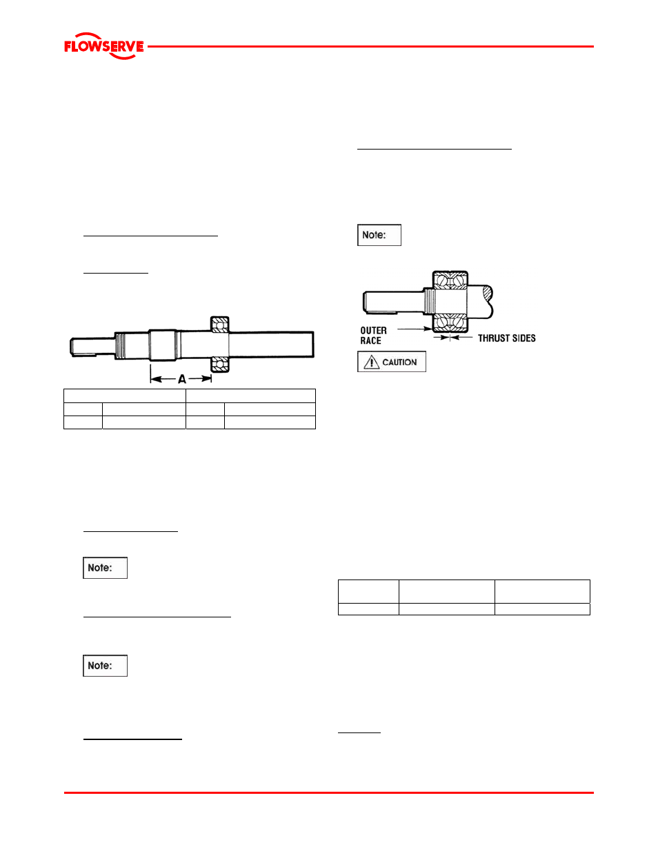
The inboard bearing must be located as shown in
figure 6-21.
Figure 6-21: Bearing position - Mark 3 design
Mark 3 standard shaft
Mark 3 duplex bearing shaft
Group A Group A
2
139 mm (5
15
/
32
in.)
2
129 mm (5
3
/
32
in.)
* Inboard bearing located against shoulder.
If the power end is equipped with single shielded
regreasable bearings, see figure 5-7 for proper
orientation of the shields
b) Install the outboard bearing retaining device onto
the shaft.
Double row bearings
Place the snap ring [2530.1] onto the outboard end
of the shaft and slide down to the inboard bearing.
The proper orientation of the snap ring
must be assured in this step. The flat side of the
snap ring must face away from the inboard bearing.
Duplex angular contact bearings
Place the bearing retainer [2530.2] onto the
outboard end of the shaft and slide down to the
inboard bearing.
The proper orientation of the bearing
retainer must be assured in this step. The small
side of the retainer must face away from the
inboard bearing.
c) Install the outboard bearing.
Double row bearings
Install the outboard bearing [3012] firmly against
the shoulder as shown in figure 6-19. If hot
bearing mounting techniques are used, steps
must be taken to ensure the outboard bearing is
firmly positioned against the shaft shoulder. The
outboard bearing, while still hot, is to be
positioned against the shaft shoulder.
Duplex angular contact bearings
Duplex angular contact bearings must be
mounted back-to-back with the wider thrust sides
of the outer races in contact with each other as
shown in figure 6-22. Only bearings designed for
universal mounting should be used. The SKF
designation is “BECB”. NTN’s designation is “G”.
A special shaft is required when using
duplex angular contact bearings.)
Figure 22
It must be understood that fixtures
and equipment used to press the bearing must be
designed so no load is ever transmitted through the
bearing balls. This would damage the bearing.
d) After the bearing has cooled below 38 °C (100 °F)
the bearing should be pressed against the shaft
shoulder. Figure 6-23 identifies the approximate
force needed to seat the bearing against the shaft
shoulder. If a press is not available the locknut
[3712] should be installed immediately after the
bearing is placed on the shaft and tightened to
ensure the bearing remains in contact with the shaft
shoulder. The locknut should then be retightened
repeatedly during the time the bearing is cooling.
Once cool the locknut should be removed.
Figure 6-23
Pump Press
force
N (lbf)
Locknut torque
Nm (lbf·ft)
Group 2
11 100 (2 500)
54 +7/-0 (40 +5/-0)
e) Install lockwasher [6541.1] and locknut [3712].
The locknut should be torqued to the value
shown in figure 6-23. One tang on the
lockwasher must be bent into a corresponding
groove on the locknut.
6.9.1.2 Bearing housing seals
Lip seals
If lip seals were used (see figure 6-13), install new lip
seals in the bearing carrier [3240] and the adapter
[1340]. The lip seals [4310.1 and 4310.2] are double lip
Page 37 of 48