2 cartridge mechanical seals, 3 component type mechanical seal – Flowserve Mark 3 User Manual
Page 39
USER INSTRUCTIONS MARK 3 High Silicon Iron ENGLISH 71569249 09-04
Configuration A: Tap 5 (top) – As shown in Section 8.
• Casing seal chamber [1100] with one chamber
hole at top
• 1 tapped split gland [4121.1] and 1 gasket
[4590.4] for top
• 1 un-tapped spit gland [4212.2]and 1 gasket
spacer [4590.5] for bottom
Configuration B: Elimination of Tap 5.
• Casing seal chamber [1100] with one chamber
hole at top
• 1 un-tapped split gland [4121.2] and 1 gasket
[4590.4] for top
• 1 un-tapped spit gland [4212.2]and 1 gasket
spacer [4590.5] for bottom
Configuration C: Tap 5 (top) and Tap 7 (bottom)
• Casing seal chamber [1100] with 3 chamber
holes
• 2 tapped split gland [4121.1] and 2 gasket
[4590.4]
Configuration D: No taps
• Casing seal chamber [1100] with no holes
• 2 un-tapped spit gland [4212.2] and 2 gasket
spacer [4590.5]
a) Install gaskets [4590.4] and spacers [4590.5] to
split gland yokes [4121] as required.
b) Install four gland fasteners [6570.6] through the
split gland yoke holes.
c) Install split gland yoke halves around the casing
seal chamber [1100].
d) Install fasteners [6570.7], lockwashers [6541.2]
and hexnuts [6580.3] finger tight.
e) Pull assembled split gland yoke against the
casing seal chamber outer lip. Hold in position
while tightening fasteners [6570.7].
6.9.2.2 Cartridge mechanical seals
Review the seal assembly instructions and drawings
provided by the seal manufacturer.
a) Install a nose cone on the end of the shaft and
then slide the cartridge seal [4200] onto the shaft
until it lightly touches the bearing housing [3200]
or adapter [1340]. See figure 6-7.
b) Install the casing [1100] to the bearing housing
adapter and clamp in place. Now install the
cartridge seal gland to the casing seal chamber
[1100] using screws [6570.6] and nuts [6580.2].
c) Install the impeller [2200] as instructed in section
6.6. Care should be taken in the handling of high
chrome iron impellers.
d) Tighten set screws on the seal to lock the rotating
unit to the shaft. Finally, remove centering clips
from the seal.
6.9.2.3 Component type mechanical seal
Review the seal assembly instructions and drawings
(seal set dimension) provided by the seal
manufacturer.
In order to properly set a component seal it is
necessary to first locate the shaft in its final axial
position. This is accomplished in the following
manner.
a) Install the casing [1100] to the bearing housing
and clamp in place.
b) Install and set the impeller [2200] clearance as
outlined in section 6.6. Put blueing on the shaft/
sleeve in the area near the face of the casing seal
chamber [casing 1100]. Scribe a mark on the
shaft at the face of the seal chamber (figure 6-24).
Figure 6-24
c) Remove the impeller and seal chamber (casing)
following the instructions given in section 6.7 and
install a nose cone onto the end of the shaft.
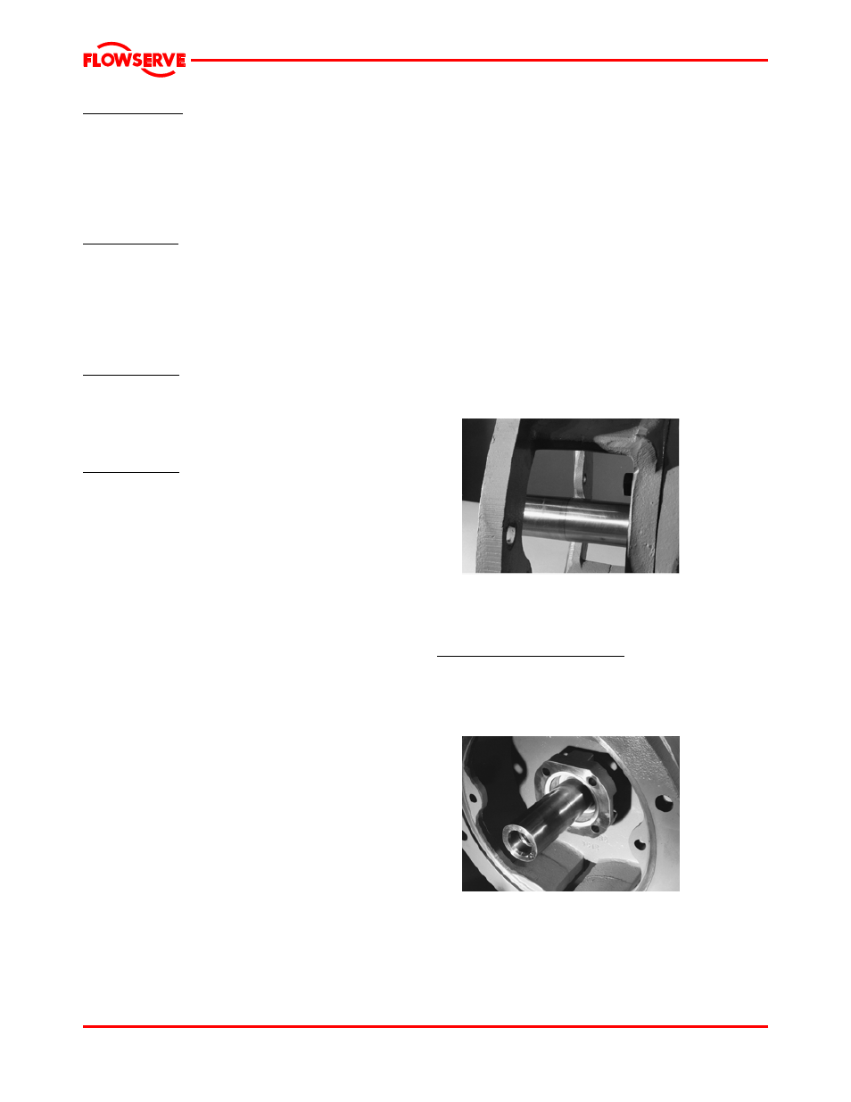
Single internal seal installation
d) Place the gland [4120] and stationary seat onto
the shaft until it lightly touches the bearing
housing adapter.
e) Install a gland gasket [4590.3] into the gland.
(See figure 6-25.)
Figure 6-25
f)
Locate the rotary seal unit onto the shaft (or sleeve)
according to the set dimension provided by the seal
manufacture. Tighten set screws on the seal to
lock the rotating unit to the shaft/sleeve.
g) Install the casing [1100] to the bearing housing
adapter and clamp in place.
Page 39 of 48