1 mechanical seal, 2 packing, 3 piping connection – seal/packing support system – Flowserve Mark 3 User Manual
Page 18: Figure 4-11, Figure 4-12, 5 piping connection - oil mist lubrication system
USER INSTRUCTIONS MARK 3 High Silicon Iron ENGLISH 71569249 09-04
4.6.6 Auxiliary piping
4.6.6.1 Mechanical seal
When the pump is intended to be equipped with a
mechanical seal, it is Flowserve standard practice to
install the mechanical seal in the pump prior to
shipment. Specific order requirements may specify
that the seal be shipped separately, or none be
supplied. It is the pump installer’s responsibility to
determine if a seal was installed. If a seal was
supplied but not installed, the seal and installation
instructions will be shipped with the pump.
Failure to ensure that a seal is installed
may result in serious leakage of the pumped fluid.
Seal and seal support system must be installed and
operational as specified by the seal manufacturer.
The stuffing box/seal chamber/gland may have ports
that have been temporarily plugged at the factory to
keep out foreign matter. It is the installer’s
responsibility to determine if these plugs should be
removed and external piping connected. Refer to the
seal drawings and or the local Flowserve
representative for the proper connections.
4.6.6.2 Packing
When the pump is intended to be equipped with shaft
packing, it is not Flowserve standard practice to
install the packing in the stuffing box prior to
shipment. The packing is shipped with the pump. It
is the pump installer’s responsibility to install the
packing in the stuffing box.
Failure to ensure that the packing is
installed may result in serious leakage of the pumped
fluid.
4.6.6.3 Piping connection – seal/packing support
system
If the pump has a seal support system
it is mandatory that this system be fully installed and
operational before the pump is started.
If packing is used:
4.6.6.3a Packing lubrication
Water, when compatible with the pumpage, should be
introduced into tap 5 (figure 4-11) at pressure 69 to
103 kPa (10 to 15 lbf/in.
2
) above the stuffing box
pressure. The gland should be adjusted to give a flow
rate of 20 to 30 drops per minute for clean fluid. For
abrasive applications, the regulated flow rate should
be 0.06 to 0.13 l/s (1 to 2 US gpm)
Figure 4-11
Tap 5
Grease lubrication, when compatible with the liquid being
pumped, may be used. Again, introduced into tap 5.
In non-abrasive applications the liquid being pumped
may be sufficient to lubricate the packing without
need for external lines. Tap 5 should be plugged.
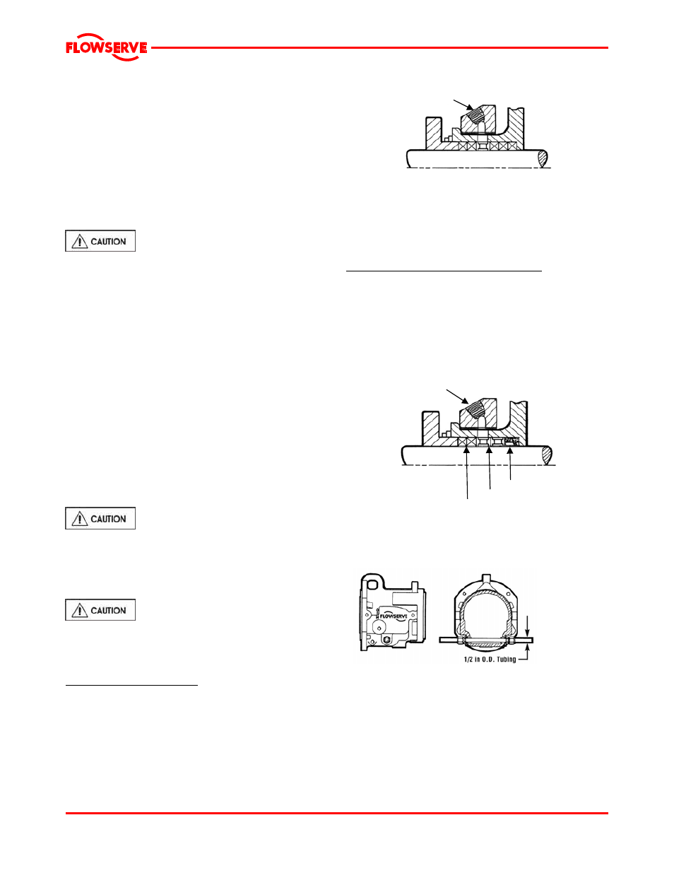
4.6.6.3b Abrasive packing arrangement
The installation procedures are the same as the
standard packing with some exceptions. A special lip
seal is installed first, followed by two seal cage
assemblies, then two of the packing rings provided
(figure 4-12). A flush line from a clean external
source should be connected via tap 5, in the top of
the stuffing box.
Figure 4-12
Tap 5
4.6.6.4 Piping connection - bearing housing
cooling system
Lip Seal
Seal Cage
Packing
Make connections as shown below. Liquid at less
than 32 °C (90 °F) should be supplied at a regulated
flow rate of at least 0.06 l/s (1 US gpm).
Figure 4-13
4.6.6.5 Piping connection - Oil mist lubrication
system
The piping connections for an oil mist lubrication
system are shown below.
Page 18 of 48