3 split gland yoke disassembly, 8 examination of parts, 1 cleaning/inspection – Flowserve Mark 3 User Manual
Page 32: 2 critical measurements and tolerances, 3 parameters that should be checked by users, 4 additional parameters checked by flowserve, 1 shaft and sleeve (if fitted)
USER INSTRUCTIONS MARK 3 High Silicon Iron ENGLISH 71569249 09-04
This is accomplished by removing the cap screws
[6570.5], which thread into the bearing housing.
Mark 3 design
This is accomplished by removing the hex nuts
[6570.5A] and the cap screws [6570.5].
cc) If lip seals [4310.1] and [4310.2] (see figure 6-13)
are used, they should be removed from the
bearing carrier and adapter and discarded.
Figure 6-13
dd) If the bearing isolators are removed from either
the bearing carrier or adapter they must not be
reused, discard appropriately.
ee) If magnetic seals are used, maintain the seals as
specified by the manufacturer.
ff) Mark 3 and Mark 3A design
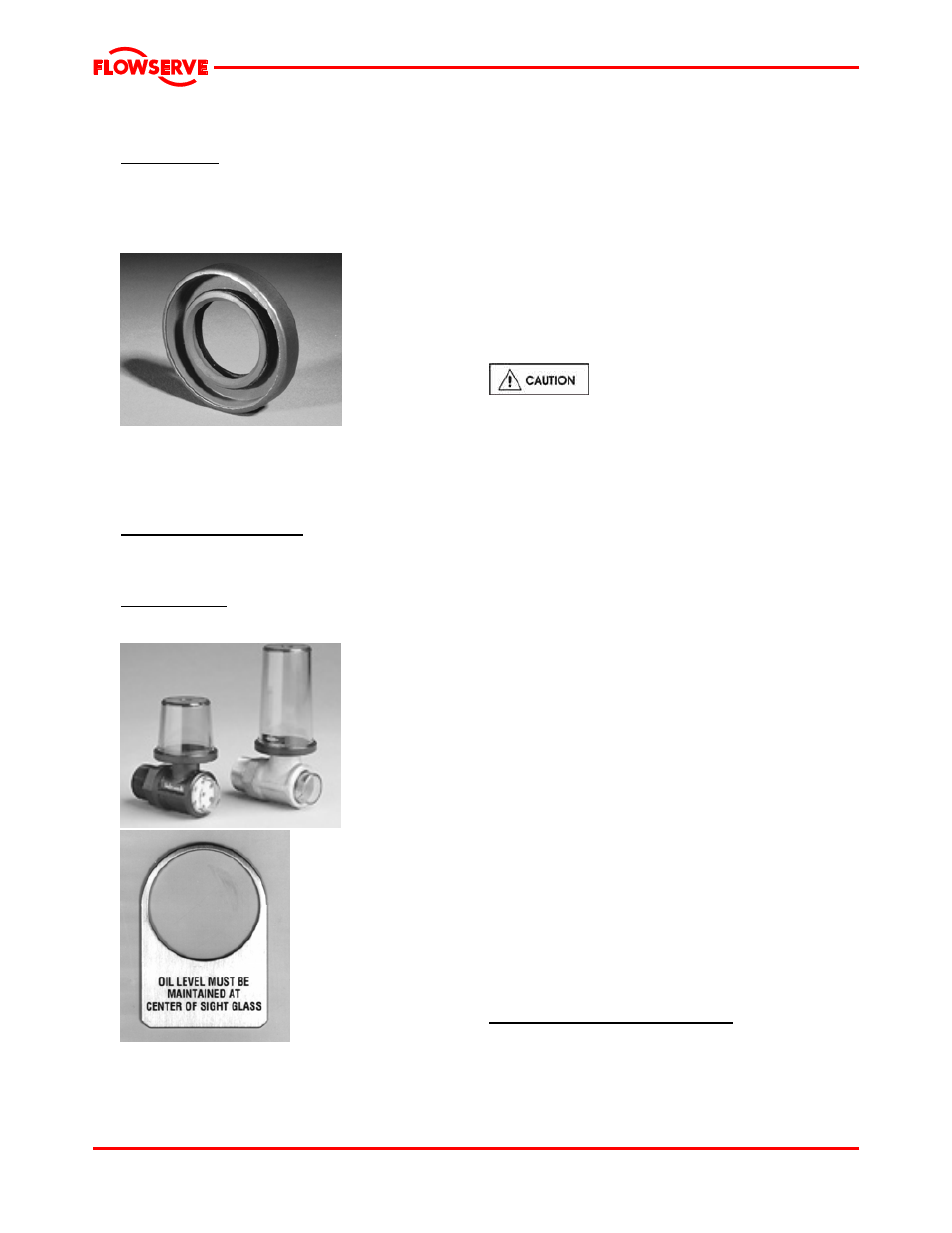
Remove the Trico oiler/site gage [3855]
(figure 6-14) and oil level tag (figure 6-15) from the
bearing housing.
ANSI 3A design
Remove the site gage [3856] (figure 5-1) and oil
level tag (figure 6-15) from the bearing housing.
Figure 6-14
Figure 6-15 - “Oil level
must be maintained at center of sight glass”
Save these parts for reuse.
6.7.3 Split Gland Yoke Disassembly
It should not be necessary to remove the split gland
yoke [4121]. If the yoke is removed, discard the
gasket(s).
6.8 Examination of parts
6.8.1 Cleaning/inspection
All parts should now be thoroughly cleaned and
inspected. New bearings, O-rings, gaskets, and lip
seals should be used. Any parts that show wear or
corrosion should be replaced with new genuine
Flowserve parts.
It is important that only non-flammable,
non-contaminated cleaning fluids are used. These
fluids must comply with plant safety and environmental
guidelines.
6.8.2 Critical measurements and tolerances
To maximize reliability of pumps, it is important that
certain parameters and dimensions are measured
and maintained within specified tolerances. It is
important that all parts be checked. Any parts that do
not conform to the specifications should be replaced
with new Flowserve parts.
6.8.3 Parameters that should be checked by
users
Flowserve recommends that the user check the
measurements and tolerances in figure 6-16
whenever pump maintenance is performed. Each of
these measurements is described in more detail on
the following pages.
6.8.4 Additional parameters checked by
Flowserve
The parameters listed below are somewhat more
difficult to measure and/or may require specialized
equipment. For this reason, they are not typically
checked by our customers, although they are
monitored by Flowserve during the manufacturing
and/or design process.
6.8.4.1 Shaft and sleeve (if fitted)
Replace if grooved, pitted or worn. Prior to mounting
bearings or installing the shaft into the bearing
housing, check the following parameters.
Diameter/tolerance, under bearings
In order to ensure proper fit between the shaft and
bearings, verify that both the inboard (IB) and
outboard (OB) shaft diameter is consistently within
the minimum/maximum values shown in figure 6-17.
Page 32 of 48