Figure 4-3, Figure 4-4 – Flowserve Mark 3 User Manual
Page 14
USER INSTRUCTIONS MARK 3 High Silicon Iron ENGLISH 71569249 09-04
e)
Assemble the stilt bolt up through hole in the
bottom plate and hold in place.
f)
Assemble the lock washer [3] and nut [2] on the
stilt bolt. Tighten the nut down on the lock
washer.
g)
After all four stilts have been assembled,
position the baseplate in place, over the floor
cups [4] under each stilt location, and lower the
baseplate to the floor.
h)
Level and make final height adjustments to the
suction and discharge pipe by first loosening the
top nuts and turning the bottom nuts to raise or
lower the baseplate.
i)
Tighten the top and bottom nuts at the lock
washer [3] first then tighten the other nuts.
j)
It should be noted that the connecting pipelines
must be individually supported, and that the stilt
mounted baseplate is not intended to support
total static pipe load.
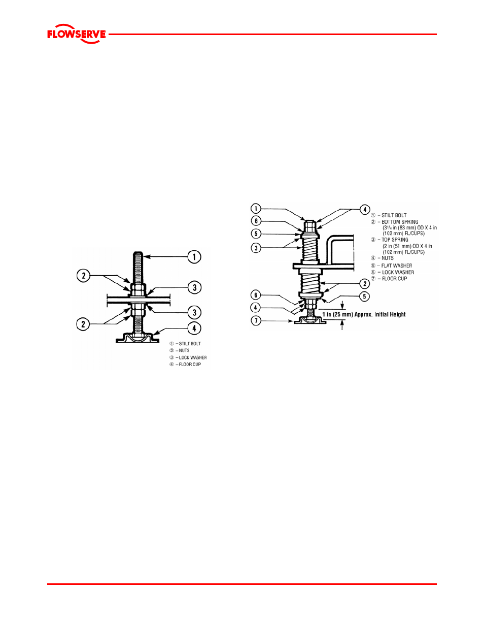
Figure 4-3
4.3.3.2 Stilt/spring mounted baseplate assembly
instructions
Refer to figure 4-4.
a)
Raise or block up baseplate/pump above the
floor to allow for the assembly of the stilts.
b)
Set the bottom nuts [4] above the stilt bolt head
[1]. This allows for 51 mm (2 in.) upward
movement for the final height adjustment of the
suction/discharge flange.
c)
Assemble the lock washer [6] flat washer [5] and
bottom spring/cup assembly [2] down over the
stilt bolt [1].
d)
Assemble the stilt bolt/bottom spring up through
hole in the bottom plate and hold in place.
e)
Assemble top spring/cup assembly [3] down
over stilt bolt.
f)
Assemble flat washer [5], lock washer [6] and
nuts [4] on the stilt bolt.
g)
Tighten down top nuts, compressing the top
spring approximately 25 mm (1 in.).
h)
After all four stilts have been assembled,
position the baseplate in place, over the floor
cups [7] under each stilt location, and lower the
baseplate down to the floor.
i)
Level and make final height adjustments to the
suction and discharge pipe by first loosening the
top nuts, and turning the bottom nuts to raise or
lower the baseplate.
j)
To make the stilt bolts more stable, tighten down
on the top nuts, compressing the top spring
approximately 25 mm (1 in.), and lock the nuts in
place.
k)
It should be noted that the connecting pipelines
must be individually supported, and that the
spring mounted baseplate is not intended to
support total static pipe loads.
Figure 4-4
4.3.3.3 Stilt/spring mounted baseplates - motor
alignment
The procedure for motor alignment on stilt or spring
mounted baseplates is similar to grouted baseplates.
The difference is primarily in the way the baseplate is
leveled.
a) Level the baseplate by using the stilt adjusters.
(Shims are not needed as with grouted
baseplates.)
b) After the base is level, it is locked in place by
locking the stilt adjusters.
c) Next the initial pump alignment must be checked.
The vertical height adjustment provided by the
stilts allows the possibility of slightly twisting the
baseplate. If there has been no transit damage
or twisting of the baseplate during stilt height
adjustment, the pump and driver should be within
0.38 mm (0.015 in.) parallel, and 0.0025 mm/mm
(0.0025 in./in.) angular alignment. If this is not
the case, check to see if the driver mounting
fasteners are centered in the driver feet holes.
d) If the fasteners are not centered there was likely
shipping damage. Re-center the fasteners and
perform a preliminary alignment to the above
tolerances by shimming under the motor for
Page 14 of 48