5 fastener torques, 6 setting impeller clearance and impeller, Replacement – Flowserve Mark 3 User Manual
Page 28
USER INSTRUCTIONS MARK 3 High Silicon Iron ENGLISH 71569249 09-04
impeller. It also contains “nose cones” which protect
shaft threads and O-rings during maintenance.
This tool kit can be ordered from your local Flowserve
sales engineer or from a Flowserve distributor or
representative.
Figure 6-1
6.5 Fastener torques
Figure 6-2: Recommended bolt torques
Item Description
Group
2
non-lubricated
[6570.2] Bearing retainer cap screws
- duplex bearings
3
⁄
16
in. – 6 Nm (4 lbf•ft)
[6570.5] Bearing housing/adapter cap
screws and nuts
½ in. – 54 Nm (40 lbf•ft)
[6570.6] Mechanical
seal
gland
studs/nuts
⅜ in. – 16 Nm (12 lbf•ft)
[6570.7] Split gland yoke screws/nuts
⅜ in. – 22 Nm (16 lbf•ft)
[6570.1] Casing
screws/nuts
⅝ in. – 47 Nm (35 lbf•ft)
[6570.3] Bearing carrier set screws
½ in. – 41 Nm (30 lbf•ft)
[6570.4] Cap screw foot
¾ in. – 217 Nm (160 lbf•ft)
[3712]
Bearing Locknut
54 +7 / -0 Nm
(40 +5 / -0 lbf•ft)
Note:
1. For lubricated or PTFE-coated threads, use 75% of the values
given.
6.6 Setting impeller clearance and
impeller replacement
A new impeller gasket [4590] must be installed
whenever the impeller has been removed from the
shaft. Impeller clearance settings may be found in
section 5.3. Impeller balancing instruction may be
found in section 6.8.
Figure 6-3
Figure 6-4
Figure 6-5
Indicator
Pattern
Rotation Equivalent To
0.1 mm (0.004 in) Axial
Movement
Figure 6.6
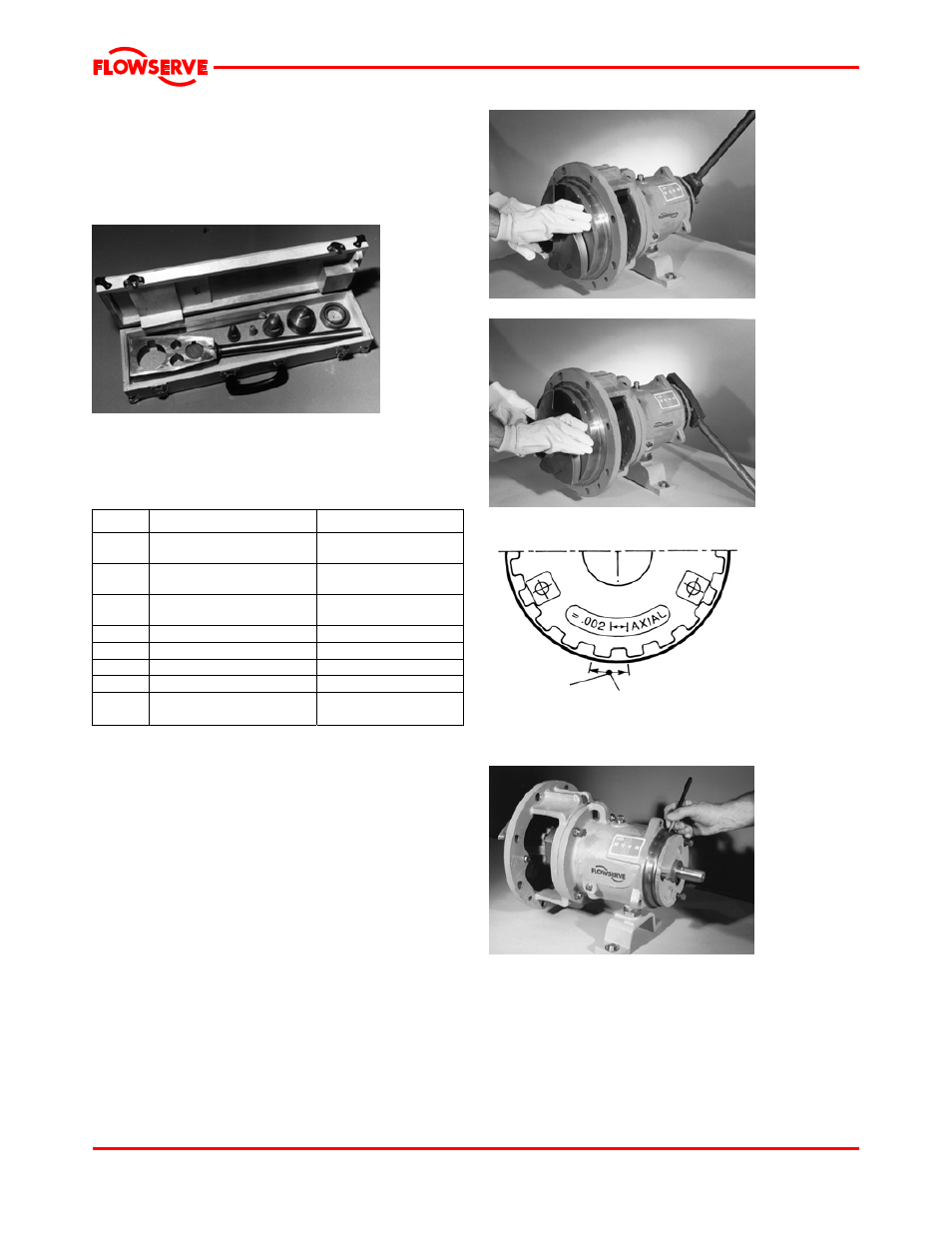
6.6.1 Installation and clearance setting for front
vane open style impeller
Install the impeller [2200] by screwing it onto the shaft
(use heavy gloves) until it firmly seats against the
shaft shoulder.
Page 28 of 48