1 trimming and assembly instructions, 6 priming and auxiliary supplies, 7 starting the pump – Flowserve Mark 3 User Manual
Page 24: 8 running or operation, 1 minimum continuous flow
USER INSTRUCTIONS MARK 3 High Silicon Iron ENGLISH 71569249 09-04
following instructions enable the user to properly fit
this guard to the pump and motor.
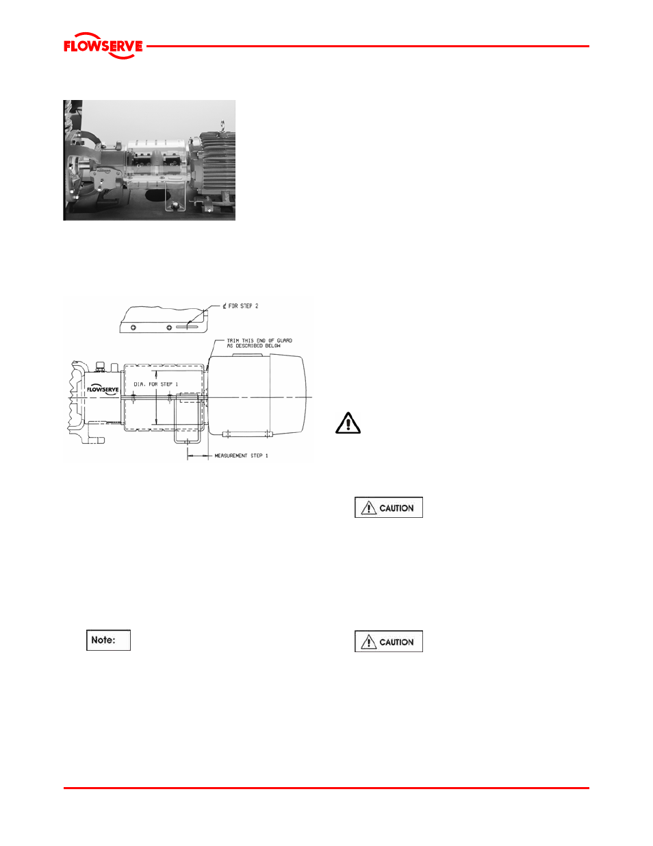
Figure 5-14
5.5.2.1 Trimming and assembly instructions
In order to correctly fit the pump/motor configuration,
each ClearGuard must be trimmed to a specific
length. This trimming is done on the motor end of the
guard as described below. (See figure 5-15.)
Figure 5-15
a) Measure minimum distance from the center of
mounting hole in the baseplate to the motor at
diameter as shown above.
b) Locate a reference center of the slot in the coupling
guard flange. Transfer measurement from step 1 to
the guard using this reference center.
c) Trim the motor end of guard according to the above
measurement. Trimming is best done with a band
saw, but most other types of manual or power saws
give acceptable results. Care must be taken to
ensure that there is no gap larger than 6 mm
(0.24 in.) between the motor and the coupling guard.
d)
If motor diameter is smaller than guard
diameter, trim guard so that it extends over the
end of the motor as far as possible.
e)
Deburr the trimmed end with a file or a sharp
knife. Care must be taken to eliminate all sharp
edges.
f)
Place the bottom and top halves of the
ClearGuard around the coupling.
g)
Install the support legs by inserting and then
rotating the top flange of the leg through the slot
in the shell flange until it comes all the way
through and locks the top and bottom together.
h)
Attach the support legs to the baseplate using
the fasteners and washers provided.
i)
Install fasteners in the holes provided to secure
the guard flanges together.
5.6 Priming and auxiliary supplies
The Mark 3 HSI centrifugal pump will not move liquid
unless the pump is primed. A pump is said to be
“primed” when the casing and the suction piping are
completely filled with liquid. Open discharge valves a
slight amount. This will allow any entrapped air to
escape and will normally allow the pump to prime, if the
suction source is above the pump. When a condition
exists where the suction pressure may drop below the
pump’s capability, it is advisable to add a low-pressure
control device to shut the pump down when the
pressure drops below a predetermined minimum.
5.7 Starting the pump
a) Open the suction valve to full open position. It is
very important to leave the suction valve open while
the pump is operating. Any throttling or adjusting of
flow must be done through the discharge valve.
Partially closing the suction valve can create
serious NPSH and pump performance problems.
THERMAL SHOCK
Rapid changes in the temperature of the liquid within
the pump can cause thermal shock, which can result
in damage or breakage of components and should be
avoided. High Silicon Iron should be heated and
cooled at a maximum rate of 55˚C (100˚F) per hour.
b)
Never operate pump with both the
suction and discharge valves closed. This could
cause an explosion.
c) Ensure the pump is primed. (See section 5.6.)
d) All cooling, heating, and flush lines must be
started and regulated.
e) Start the driver (typically, the electric motor).
f) Slowly open the discharge valve until the desired
flow is reached, keeping in mind the minimum
continuous flow listed in section 3.4.
g)
It is important that the discharge valve
be opened within a short interval after starting the
driver. Failure to do this could cause a dangerous
build up of heat, and possibly an explosion.
5.8 Running or operation
5.8.1 Minimum continuous flow
Minimum continuous stable flow is the lowest flow at
which the pump can operate and still meet the bearing
Page 24 of 48