The asme b73.1m, paragraph 5.1.4, 2 bearings, 3 impeller balancing – Flowserve Mark 3 User Manual
Page 33: 4 bearing housing/carrier
USER INSTRUCTIONS MARK 3 High Silicon Iron ENGLISH 71569249 09-04
A micrometer should be used to check these outside
diameter (OD) dimensions on the shaft.
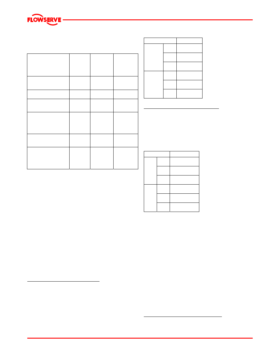
Figure 6-16
Topic
ASME
B73.1M
standard
mm (in.)
Suggested
by major
seal
vendors
mm (in.)
Suggested
and/or
provided by
Flowserve
mm (in.)
Shaft
Diameter tolerance,
under bearings
n/s
0.005 (0.0002)
Impeller
Balance
See note 1
Bearing housing
Diameter (ID) tolerance
at bearings
n/s
0.013 (0.0005)
Power end assembly
Shaft runout
Shaft sleeve runout
Radial deflection - static
Shaft endplay
0.05 (0.002)
0.05 (0.002)
n/s
n/s
0.03 (0.001)
0.05 (0.002)
0.076 (0.003)
0.05 (0.002)
0.05 (0.002)
0.05 (0.002)
0.05 (0.002)
Seal chamber
Face squareness to shaft
Register concentricity
0.08 (0.003)
0.03 (0.001)
0.13 (0.005)
0.08 (0.003)
0.13 (0.005)
Complete pump
Shaft movement caused
by pipe strain
Alignment
Vibration at bearing housing
n/s
n/s
See note 3
0.05 (0.002)
0.05 (0.002)
See note 2
See note 3
n/s = not specified.
1. The maximum values of acceptable unbalance are:
1500 r/min: 40 g·mm/kg (1800 r/min: 0.021 oz-in/lb) of mass.
2900 rpm: 20 g·mm/kg (3600 rpm: 0.011 oz-in/lb) of mass.
Flowserve performs a single plane spin balance on most
impellers. The following impellers are exceptions: 10X8-14,
10X8-16 and 10X8-16H. On these Flowserve performs a two
plane dynamic balance, as required by the ASME B73.1M
standard. All balancing, whether single or two plane, is
performed to the ISO 1940 Grade 6.3 tolerance criteria.
2. The ASME B73.1M standard does not specify a recommended
level of alignment. Flowserve recommends that the pump and
motor shafts be aligned to within 0.05 mm (0.002 in.) parallel FIM
(full indicator movement) and 0.0005 mm/mm (0.0005 in./in.)
angular FIM. Closer alignment will extend MTBPM. For a
detailed discussion of this subject see the Alignment section of
this manual.
3. The ASME B73.1M, paragraph 5.1.4.
6.8.4.2 Bearings
It is recommended that bearings not be re-used after
removal from the shaft. Prior to mounting bearings,
check the following parameters.
Diameter/tolerance, inside diameter
In order to ensure proper fit between bearings and
the shaft, verify that the inside diameter (ID) of both
the IB and OB bearing are consistently within the
minimum/maximum values shown in figure 6-17. An
inside caliper should be used to check these ID
diameters on the bearings.
Figure 6-17
Group
2
Bearing
50.000/49.987
(1.9685/1.9680)
Shaft
50.013/50.003
(1.9690/1.9686)
OB
bearing/
shaft
mm (in.)
Fit
0.026T/0.003T
(0.0010T/0.0001T)
Bearing
50.000/49.987
(1.9685/1.9680)
Shaft
50.013/50.003
(1.9690/1.9686)
IB
bearing/
shaft
mm (in.)
Fit
0.026T/0.003T
(0.0010T/0.0001T)
Diameter/tolerance, outside diameter
In order to ensure proper fit between bearings and
the bearing housing, verify that the OD on both the IB
and OB bearings are consistently within the
minimum/maximum values shown in figure 6-18. A
micrometer should be used to check these outside
diameter (OD) dimensions on the bearings.
Figure 6-18
Group
2
Bearing
110.000/109.985
(4.3307/4.3301)
Carrier
110.007/110.022
(4.3310/4.3316)
OB
bearing/
carrier
mm (in.)
Fit
0.037L/0.007L
(0.0015/0.0003L)
Bearing
110.000/109.985
(4.3307/4.3301)
Housing
110.007/110.022
(4.3310/4.3316)
IB
bearing/
housing
mm (in.)
Fit
0.037L/0.007L
(0.0015L/0.0003L)
6.8.4.3 Impeller balancing
Shaft whip is deflection where the centerline of the
impeller is moving around the true axis of the pump.
It is not caused by hydraulic force but rather by an
imbalance with the rotating element. Shaft whip is
very hard on the mechanical seal because the faces
must flex with each revolution in order to maintain
contact. To minimize shaft whip it is imperative that
the impeller is balanced. All impellers manufactured
by Flowserve are balanced after they are trimmed. If
for any reason, a customer trims an impeller, it must
be re-balanced. See note 1 under figure 6-16
regarding acceptance criteria.
6.8.4.4 Bearing housing/carrier
Prior to installing the shaft into the bearing housing,
check the following parameters.
Diameter/tolerance, at bearing surface
In order to ensure proper fit between the bearing
housing/carrier and the bearings, verify that the ID of
Page 33 of 48