3 impeller clearance, 4 direction of rotation, 1 rotation check – Flowserve Mark 3 User Manual
Page 23: 2 coupling installation, 5 guarding, 1 clam shell guard - standard, 2 clearguard™ - optional
USER INSTRUCTIONS MARK 3 High Silicon Iron ENGLISH 71569249 09-04
5.3 Impeller clearance
The impeller clearance was set at the factory based
on the application temperature at the time the pump
was purchased (see figure 5-10). For an open
impeller the clearance is set to the front cover
(suction side). If the process temperature changes
the impeller clearance must be reset, see section 6.6.
Figure 5-10: Impeller clearance settings
Temperature °C (°F)
Clearance mm (in.)
< 93 (200)
0.46 ± 0.08 (0.018 ± 0.003)
93 to 121 (200 to 250)
0.53 (0.021)
122 to 149 (251 to 300)
0.61 (0.024)
150 to 176 (301 to 350)
0.69 (0.027)
177 to 204 (351 to 400)
0.76 (0.030)
205 to 232 (401 to 450)
0.84 (0.033)
>232 (450)
0.91 (0.036)
Notes:
1. Rotation of bearing carrier from center of one lug to center of
next results in axial shaft movement of 0.1 mm (0.004 in.).
2. Open impeller set to suction cover.
5.4 Direction of rotation
5.4.1 Rotation check
It is absolutely essential that the
rotation of the motor be checked before connecting
the shaft coupling. Incorrect rotation of the pump, for
even a short time, can dislodge and damage the
impeller, casing, shaft and shaft seal. All Mark 3
pumps turn clockwise as viewed from the motor end.
A direction arrow is cast on the front of the casing as
shown in figure 5-11. Make sure the motor rotates in
the same direction.
Figure 5-11
5.4.2 Coupling installation
The coupling (figure 5-12) should be
installed as advised by the coupling manufacturer.
Pumps are shipped without the spacer installed. If
the spacer has been installed to facilitate alignment,
then it must be removed prior to checking rotation.
Remove all protective material from the coupling and
shaft before installing the coupling.
Figure 5-12
5.5 Guarding
Power must never be applied to the
driver when the coupling guard is not installed.
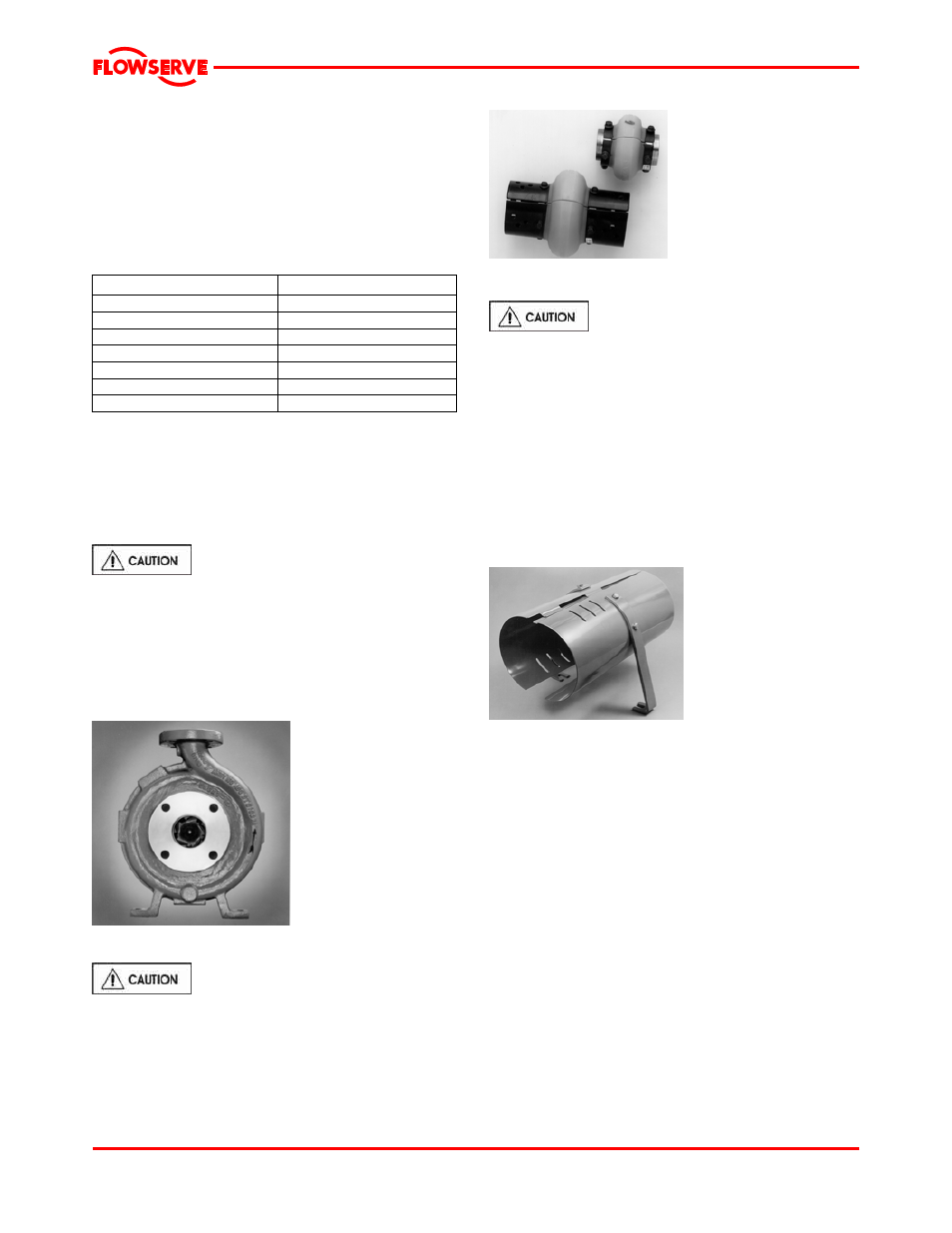
5.5.1 Clam shell guard - standard
The standard coupling guard for all Mark 3 pumps is
the “clam shell” design and is shown in figure 5-13. It
is hinged at the top and it can be removed by
loosening one of the foot bolts and sliding the support
leg out from under the cap screw. Note that the foot
is slotted. The leg can then be rotated upward and
half of the guard can be disengaged (unhinged) from
the other. Only one side of the guard needs to be
removed. To reassemble simply reverse the above
procedure.
Figure 5-13
Flowserve coupling guards are safety devices intended
to protect workers from inherent dangers of the rotating
pump shaft, motor shaft and coupling. It is intended to
prevent entry of hands, fingers or other body parts into a
point of hazard by reaching through, over, under or
around the guard. No standard coupling guard provides
complete protection from a disintegrating coupling.
Flowserve cannot guarantee their guards will
completely contain an exploding coupling.
The coupling guard shown in figure 5-13 conforms to
the USA standard ASME B15.1, “Safety standard for
mechanical power transmission apparatus.”
Flowserve manufacturing facilities worldwide conform
to local coupling guard regulations.
5.5.2 ClearGuard™ - optional
Flowserve offers as an option a ClearGuard™, which
allows you to see the condition of the coupling (see
figure 5-14). This guard can be used in place of the
existing clamshell guard described above. The
Page 23 of 48