48 pathfi nder matrix – FSR PATHFINDER Covers 12X8 THROUGH 32X32 User Manual
Page 48
48
Pathfi nder Matrix
B
A
C
K
N
A
V
A
D
J
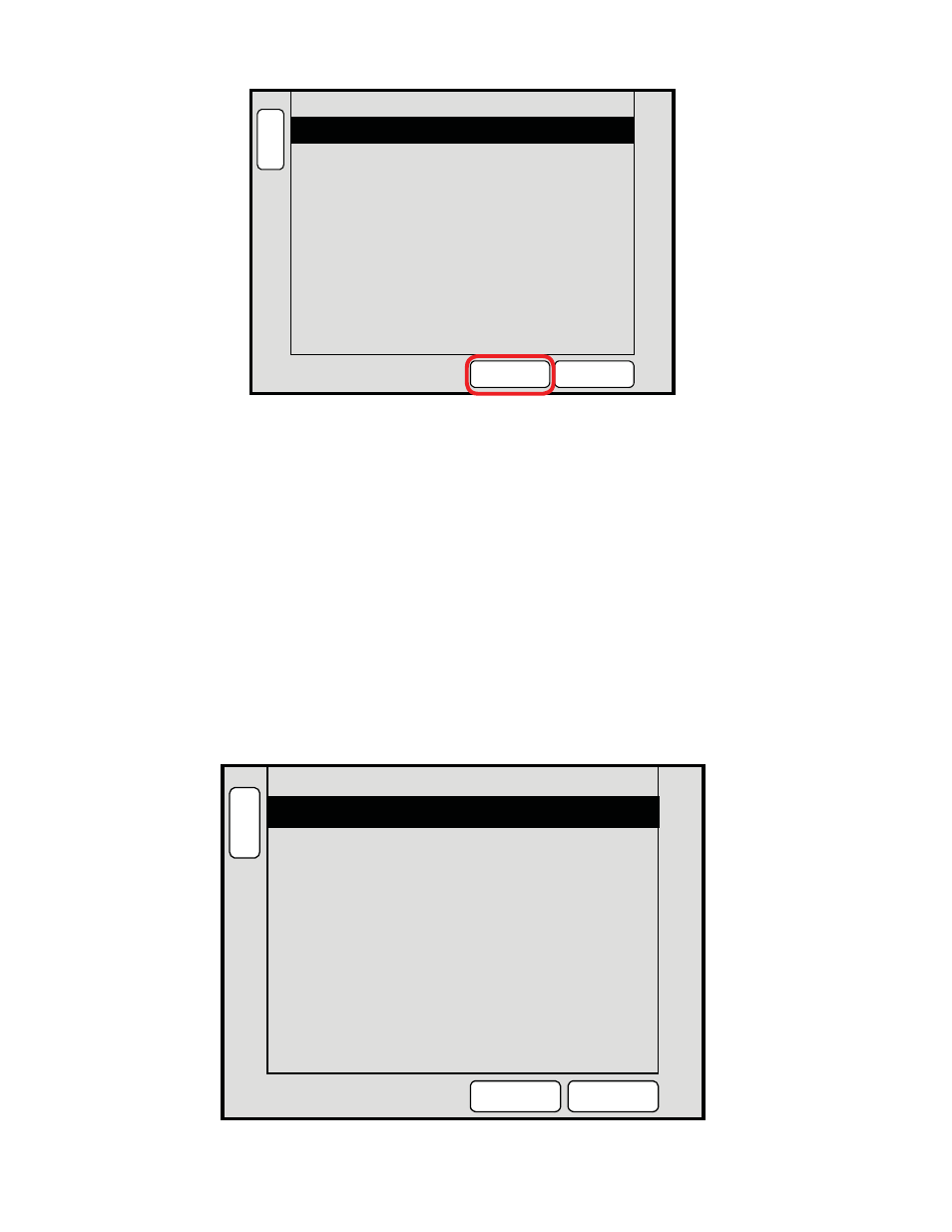
ETHERNET SETUP
IP Address
192.168.0.243
NEXT
IP QUAD
23
IP Port Number
TEST
COMM
Set the IP Address to 192.168.0.243 using the bottom rotary encoder and the “NEXT IP QUAD”
button to go from one fi eld to the next. When the IP address is set and the IP Port Number is set to
‘23’ press the ‘TEST COMM’ button to establish communications between the controller and the
Pathfi nder. A popup window will come up with the confi guration of the Pathfi nder.
2D.) Output Patch Setup
The OUTPUT PATCH setup is used to defi ne which outputs on the Pathfi nder are used for which
Eagles. That is which Pathfi nder outputs are used for inputs for which Eagle 200.
Use the BACK button to return to the “ROUTER SPECIFICATION” screen. Press the “OUTPUT
PATCH” button to bring up the “OUTPUT PATCH” menu.
B
A
C
K
N
A
V
A
D
J
OUTPUT PATCH
Router Output
1
DELETE
PATCH
E200 1
Device ID
FSR 01
1
E200 Input
[ N/A ]
Mixer Layer
E200 Input is mapped to
FSR 01 Output 1
Set Device ID to NONE to define
the Router Output as an AUX.
ADD
PATCH