Typical clock setting information – GAI-Tronics LE200, LE200-FSR, LE200-FLR Page/Party Line Extenders User Manual
Page 33
Pub. 42004-701L2F
M
ODEL
LE200
S
ERIES
W
ALL
-M
OUNT
P
AGE
/P
ARTY
®
L
INE
E
XTENDERS
P
AGE
31 of 50
f:\standard ioms - current release\42004 instr. manuals\42004-701l2f.doc
04/09
Typical Clock Setting Information
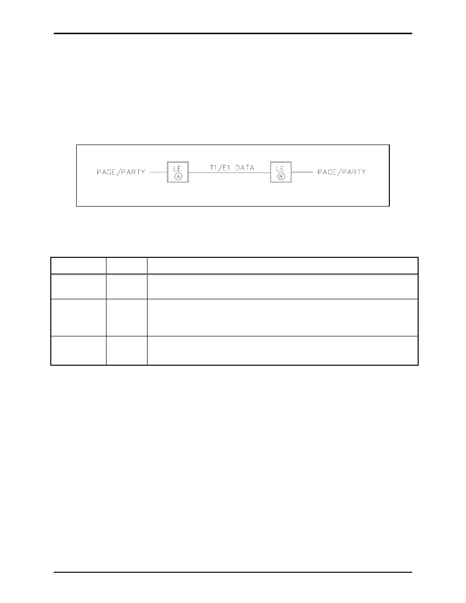
The following section shows the most common line extender connection schemes and the expected T1/E1
and LVDS data line parameters for each. Consult the applicable tables above to determine the correct
switch settings. Consult GAI-Tronics for technical support of connection schemes not shown in this
manual.
Point-to-Point Page/Party
®
System Connection
Figure 10. Point-to-Point Page/Party
®
System Connection
Table 36. Point-to-Point Page/Party
®
System Connection Table
Parameter Switch
Configuration
Description
T1 Line
Length
SW2
Determined by installation distance between LE200s.
T1/E1 Clock
Source
SW3-1
SW3-2
• Unit A is the master clock source: SW3-1 (open) SW3-2 (open)
• Unit B uses the T1/E1 clock from Unit A: SW3-1 (closed) SW3-2
(closed)
LVDS Clock
Source
SW3-3
SW3-4
Not used - disable both LVDS “in” and “out”: SW3-3 (open) SW3-4 (open)