Summary of pc board connections and settings – GAI-Tronics LE200, LE200-FSR, LE200-FLR Page/Party Line Extenders User Manual
Page 38
Pub. 42004-701L2F
M
ODEL
LE200
S
ERIES
W
ALL
-M
OUNT
P
AGE
/P
ARTY
®
L
INE
E
XTENDERS
P
AGE
36 of 50
f:\standard ioms - current release\42004 instr. manuals\42004-701l2f.doc
04/09
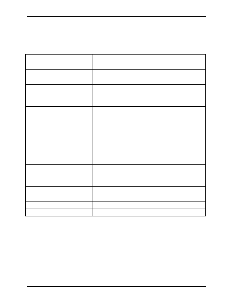
Summary of PC Board Connections and Settings
Table 39. Page/Party Termination PCBA (Model 69441-xxx)
Refer to Figure 5 for component locations.
Designator Type
Function
J1
DB-25 connector
Connect to J4 on Main PCBA (69443-xxx) via ribbon cable.
P1
Jumper clip
Party line #3 line balance resistor enabled/disabled
P2
Jumper clip
Party line #2 line balance resistor enabled/disabled
P3
Jumper clip
Party line #4 line balance resistor enabled/disabled
P4
Jumper clip
Party line #1 line balance resistor enabled/disabled
P6
Jumper clip
Party line #5 line balance resistor enabled/disabled
P7
Jumper clip
Page line balance resistor enabled/disabled
P5 & P8
Terminal block
Page Line - Terminals 1 and 2
Party Line 1 - Terminals 3 and 4
Party Line 2 - Terminals 5 and 6
Party Line 3 - Terminals 7 and 8
Party Line 4 - Terminals 9 and 10
Party Line 5 - Terminals 11 and 12
R3
Potentiometer
Party line #3 line balance resistance
R4
Potentiometer
Party line #2 line balance resistance
R19
Potentiometer
Party line #4 line balance resistance
R20
Potentiometer
Party line #1 line balance resistance
R23
Potentiometer
Party line #5 line balance resistance
R24
Potentiometer
Page line, line balance resistance
TB1
Terminal block
Chassis ground - Terminals 1 and 2
TB2
Terminal block
Chassis ground - Terminals 1 and 2