Settings checklist – GAI-Tronics LE200, LE200-FSR, LE200-FLR Page/Party Line Extenders User Manual
Page 44
Pub. 42004-701L2F
M
ODEL
LE200
S
ERIES
W
ALL
-M
OUNT
P
AGE
/P
ARTY
®
L
INE
E
XTENDERS
P
AGE
42 of 50
f:\standard ioms - current release\42004 instr. manuals\42004-701l2f.doc
04/09
Settings Checklist
The following tables (Table 42 through Table 48) have been included to serve as a system setting
checklist. After determining the appropriate settings for your system, you may record them below for
future reference.
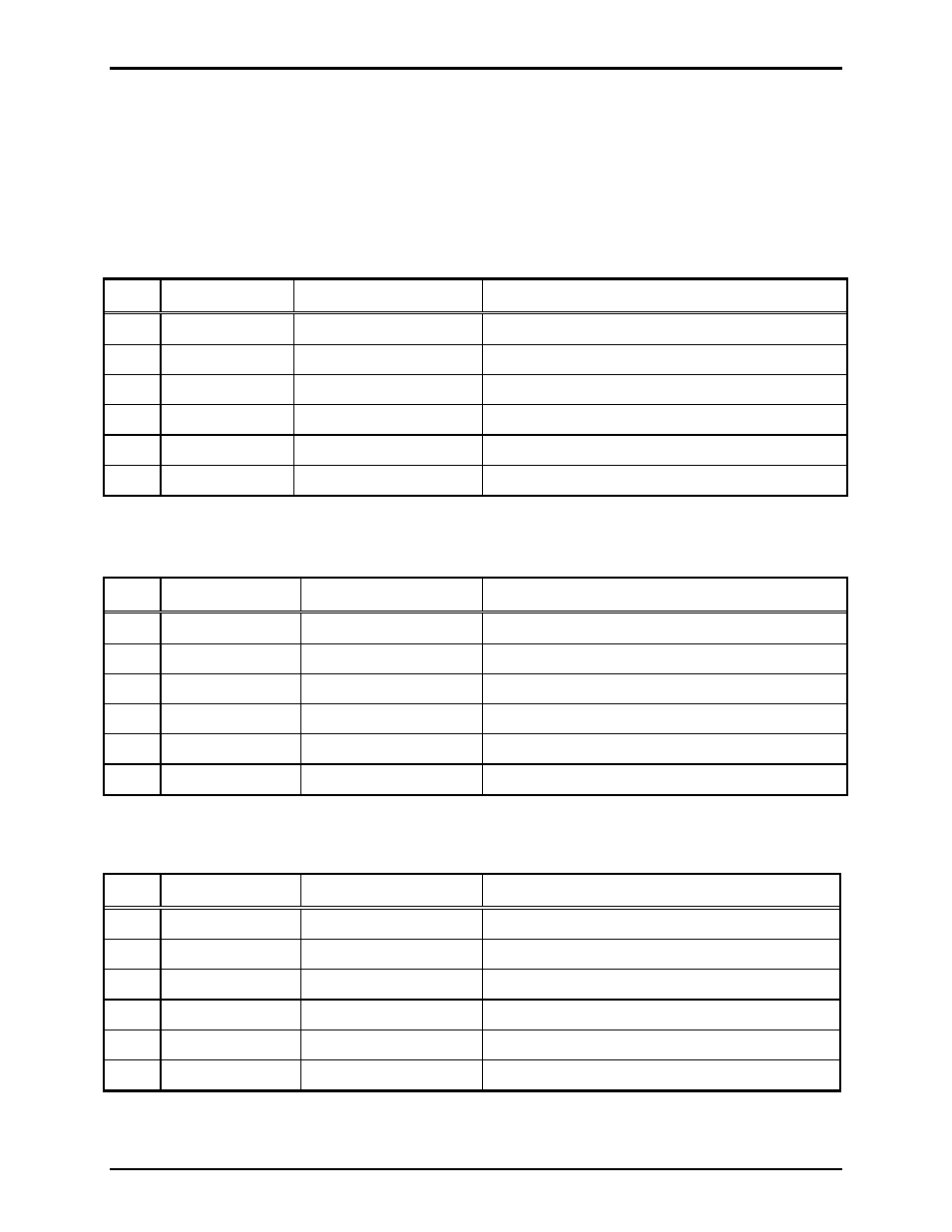
Table 42. Line Balance Resistor Enable on 69441-xxx PCBA
Header Setting
Note
P1
Party Line #3
P2
Party Line #2
P3
Party Line #4
P4
Party Line #1
P6
Party Line #5
P7
Page
Line
Table 43. Line Balance Resistance on 69441-xxx PCBA
Potentiometer
Setting
Note
R3
Party Line #3
R4
Party Line #2
R19
Party Line #4
R20
Party Line #1
R23
Party Line #5
R24
Page
Line
Table 44. Off-hook and Ground Fault Detection on 69443-xxx PCBA
Header Setting
Note
P5
Page line ground fault detector
P6, P7
Party line #5 off-hook detector
P8, P9
Party line #4 off-hook detector
P10, P11
Party line #3 off-hook detector
P12, P13
Party line #2 off-hook detector
P14, P15
Party line #1 off-hook detector