GAI-Tronics LE200, LE200-FSR, LE200-FLR Page/Party Line Extenders User Manual
Page 45
Pub. 42004-701L2F
M
ODEL
LE200
S
ERIES
W
ALL
-M
OUNT
P
AGE
/P
ARTY
®
L
INE
E
XTENDERS
P
AGE
43 of 50
f:\standard ioms - current release\42004 instr. manuals\42004-701l2f.doc
04/09
Board Edge Rotary Switch SW1 on 69443-xxx PCBA
Set to “0” during normal operation.
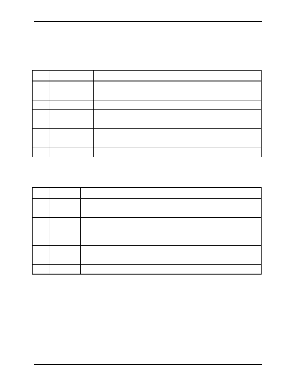
Table 45. Board Edge DIP Switch SW2 on 69443-xxx PCBA
Switch
Setting
Note
SW2-1
T1 line length
SW2-2
T1 line length
SW2-3
T1 line length
SW2-4
T1/E1 receive equalizer gain limit
SW2-5
Page line transmission direction hold time
SW2-6
Page line transmission direction hold time
SW2-7
Page line peak voltage level detection threshold
SW2-8
Open (Up)
Used during testing only.
Table 46. Internal DIP Switch SW3 on 69443-xxx PCBA
Switch
Setting
Note
SW3-1
Use T1/E1 clock
SW3-2
T1/E1
master/slave
SW3-3
Use LVDS clock
SW3-4
Enable LVDS “out”
SW3-5
Monitor
volume
SW3-6
Monitor
volume
SW3-7
Monitor
volume
SW3-8
Monitor
volume