Pump control i/o printed circuit board, Figure 5-5: pump control i/o cover plate and pcb – Gasboy Site Controller III Start-Up User Manual
Page 54
Advertising
Jumpers & Switch Settings
Page 42
MDE-4375 CFN Series Site Controller III Start-Up Manual · June 2005
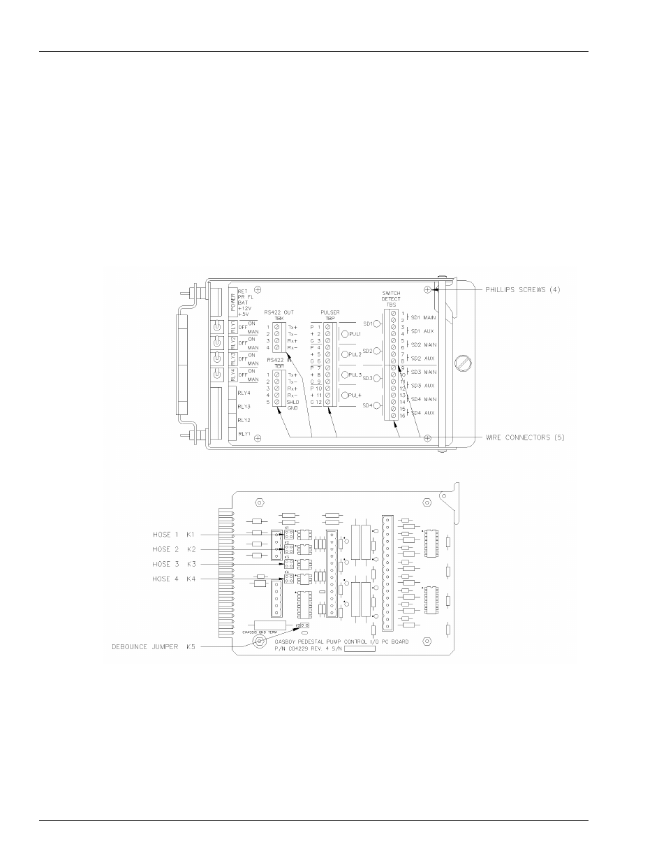
Pump Control I/O Printed Circuit Board
The Pump Control I/O PCB, shown in
, consists of two parts: the PCB itself and a
cover plate. In order to set the jumpers and switches on the I/O PCB, you must remove all the
connectors and the cover plate.
1
Remove the five green connectors from the front of the Pump Control I/O board. Remove the
board from the card cage in the same manner as the EXPMUX Pump Control CPU board.
2
Remove the four Phillips screws securing the cover plate to the PCB and remove the cover
plate.
Figure 5-5: Pump Control I/O Cover Plate and PCB
Advertising