Torch setup 2-8 duramax retrofit torch – Hypertherm HRT User Manual
Page 26
Torch seTup
2-8
Duramax Retrofit Torch
Operator Manual
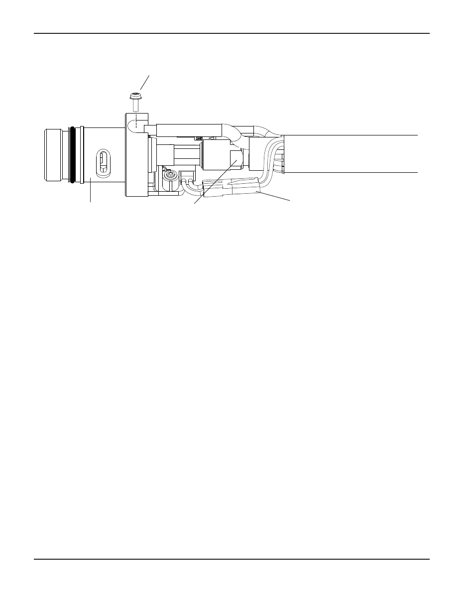
7. Disconnect the wire connector for the cap‑sensor switch.
8. Use a #2 Phillips screwdriver to remove the screw that secures the torch’s pilot wire to the
torch body.
9. Use 1/4‑inch and 3/8‑inch wrenches, or adjustable wrenches, to loosen the nut that secures
the gas supply line to the torch lead. Set the torch body aside.
10. Slide the coupler and positioning sleeve off the front of the torch lead.
11. Slide the coupler over the torch lead.
12. Reconnect the gas line to the torch lead.
13. Reattach the torch’s pilot wire to the torch body using the screw.
14. Reconnect the cap‑sensor switch’s wire connector.
15. Slide the mounting sleeve over the front of the torch body. Align the slot on the front of the
mounting sleeve (next to one of the three screw holes) with the cap‑sensor plunger on the
torch body.
16. Attach the mounting sleeve to the torch body using the three screws.
17. Screw the coupler into the mounting sleeve.
18. Screw the strain relief nut into the coupler.
19. Screw the strain relief body into the strain relief nut.
Gas supply line
connection
Torch head
Pilot wire
terminal screw
Wire connector for
cap‑sensor switch