Measuring system response, Transfer function snapshot dialog – Metric Halo SpectraFoo User Manual
Page 71
The Transfer Function
71
The equalizer in this setup is used to correct the response of the system. The switch above the pre-amp is used
to select between the output of the equalizer and the output of the test mic.
Measuring System Response
1. Open the Transfer Function window if it is not already open. Open the Transfer Function Controls
window.
2. Flatten the system equalizer or bypass it. We want to measure the un-equalized response of the system.
3. Set the response input channel to the output of the test mic. You can do this by selecting the proper input
channel in the Transfer Function Controls window (if you are using multi–channel input hardware) or by
routing your test mic to the computer input using an external routing system (e.g. a patch bay or a mixer).
4. Set the transfer function source channel to your signal source and turn on your signal source. Make
sure that the signal source is a broadband source like pink noise or pop music. Classical music does not
work as well. You must also ensure that the source is louder, on average than the environmental noise.
5. Make sure that you are getting both the source and response signal into Foo. You can use a level meter
instrument to make sure that you are getting signal. Check to see that the input levels of the two signals
are reasonably equal in level. You can eyeball this with the level meter or you can use a power-balance
meter to balance the input levels.
6. Adjust the Avg. Power Cutoff slider (in the Transfer Function Controls window) so that the pointer is in
the middle. This will allow you to get an accurate time delay calculation. Click the Compute Delay…
button. The Delay Finder will appear and automatically compensate for the acoustic delay.
7. Adjust the Avg. Power Cutoff slider (in the Transfer Function Controls window) so that the pointer is
near the left hand end of the slider. This will help the MBM thresholding system reject environmental
noise. If the traces are not moving at all, select Age from the Fade pop-up menu. Ensure that the traces
are flashing bright green all over the entire audio bandwidth. If they are not, decrease the Avg. Power
Cutoff slider until the traces start flashing. (You do not want the trace to be completely bright green
– just flashing). Adjust the Avg. Rate slider so the pointer is near the middle of the slider. This will
cause the Transfer Function to average over a reasonable period of time. After a short period of time
the measurement should settle down. If all is well, the coherence should be near the top of the graph
for most of the audio band. If you are using music, you may not see much activity in the very high
end (above 16kHz).
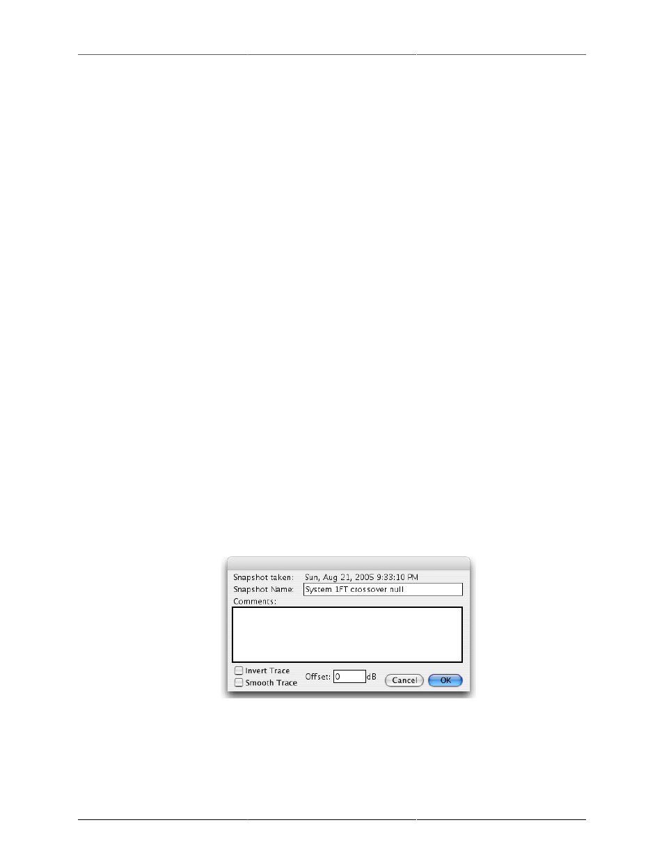
8. Click the Take Snapshot… button in the Transfer Function window. The Transfer Function Snapshot
dialog will appear:
Figure 4.30: Transfer Function snapshot dialog
Enter a descriptive name for the snapshot (e.g. “Control Room Response”). The time and date of the
Snapshot is automatically logged. You can enter any comments pertinent to the snapshot in the com-
ments box. You can also tell the system to smooth the snapshot data (when it is displayed) and to invert
the snapshot data (when it is displayed).