Programming, Vav/zone controller setpoint screens, Sa controller operator interface 50 – Orion System SA Controller User Manual
Page 50: Zone
Zone
Zone
Programming
SA Controller Operator Interface
50
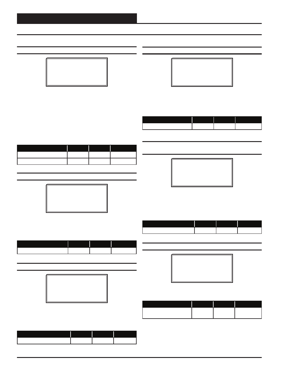
Setpoint Screen #11 - Zone Alarm Offsets
XX Box Spts IDXXXX
Zone Alarm Offsets
Hi Zone......: XXºF
Lo Zone......: XXºF
The VAV/Zone Controller can be setup to generate an alarm anytime the
box goes into the Occupied Mode and the Zone Temperature exceeds
the user-defi ned alarm limits for a user-defi ned period of time. A High
Temperature Alarm Setpoint is created by adding the Hi Zone Alarm
offset to the current Cooling Setpoint. The Low Temperature Alarm
Setpoint is created by adding the Lo Zone Alarm offset to the cur-
rent Heating Setpoint. If the zone temperature exceeds either of these
limits for a period defi ned by the Alarm Delay setpoint, the controller
can generate an alarm callout if all the optional hardware components
required for this to occur are installed.
Description
Minimum
Default
Maximum
Hi Zone Alarm
+1ºF
+30ºF
+50ºF
Lo Zone Alarm
-1ºF
-30ºF
-50ºF
Setpoint Screen #12 - Zone Alarm Delay
XX Box Spts IDXXXX
Zone Alarm Delay
Must Be Out Of
Limits For.: XXX Min
As mentioned above, if you confi gure the controller to generate zone
temperature alarms, this is the amount of time after the box goes into the
Occupied Mode that the temperature must be outside the alarm limits
before an alarm is generated.
Description
Minimum
Default
Maximum
Out of Limits
1 Min
30 Min
300 Min
Setpoint Screen #13 - Day/Night Schedule
XX Box Spts IDXXXX
Day/Night Schedule
Control #: X
0=AHU 1-5=Scheduler
This screen allows you to set the VAV/Zone controller to operate on
a remote schedule instead of the schedule that is contained in the SA
Controller. Enter
<0>
to operate on the AHU schedule. Enter
<1-5>
to
use an external schedule. A GPC Plus is required for schedules 1-5.
Description
Minimum
Default
Maximum
Schedule Control Number
0
0
1 to 5
Setpoint Screen #14 - Maximum Slide Offset
XX Box Spts IDXXXX
Maximum Slide Offset
Effect on Spt.: XºF
If the Flush Mount Wall Sensor has the optional Setpoint Slide Adjust,
this is the maximum amount you can adjust the heating and cooling
setpoints up or down as the slide is moved from the center position to
its full up or down position.
Description
Minimum
Default
Maximum
Effect on SP
0ºF
0ºF
6ºF
Setpoint Screen #15 - Push-Button Override
Duration
XX Box Spts IDXXXX
Push-Button Override
Duration : X.X Hr
If the Flush Mount Wall Sensor has the optional Push-Button Over-
ride, this is the amount of the VAV/Zone Controller will resume using
its Occupied Setpoints during unoccupied mode. This will generate a
call for the Air Handler to start its fan and provide heating or cooling,
depending on how you confi gure the Air Handler.
Description
Minimum
Default
Maximum
Duration
0.0 Hr
0.0 Hr
8.0 Hr
Setpoint Screen #16 - Maximum EMS Offset
XX Box Spts IDXXXX
Maximum EMS Setpoint
Offset...: XXºF
If the Energy Management System (EMS) is activated, the heat and cool
setpoints can be spread apart by this amount.
Description
Minimum
Default
Maximum
Maximum EMS Setpoint
Offset
0ºF
0ºF
30ºF
VAV/Zone Controller Setpoint Screens