Programming, Minilink pd confi guration screens, Sa controller operator interface – Orion System SA Controller User Manual
Page 55: Minilink pd confi guration
SA Controller Operator Interface
Programming
55
MiniLink PD Confi guration Screens
MiniLink PD Confi guration
In order to correctly setup the MiniLink PD, you must fi rst confi g-
ure several parameters in regard to the type of system and operating
parameters for the system it is installed on. Most of these values and
operating parameters are only set once at the initial system setup and
are never changed.
System Manager Instructions
From any Menu Screen, press the
<Setpoints>
button. The Unit Selec-
tion Screen will appear requesting that you enter the unit ID number. All
MiniLink PDs are set at address 60. Enter the correct unit loop number
for the loop the MiniLink Polling Device is connected to (Loop 1 you
would enter 1) and then enter
<60>
. Press
<Enter>
. You will see the
screen shown below.
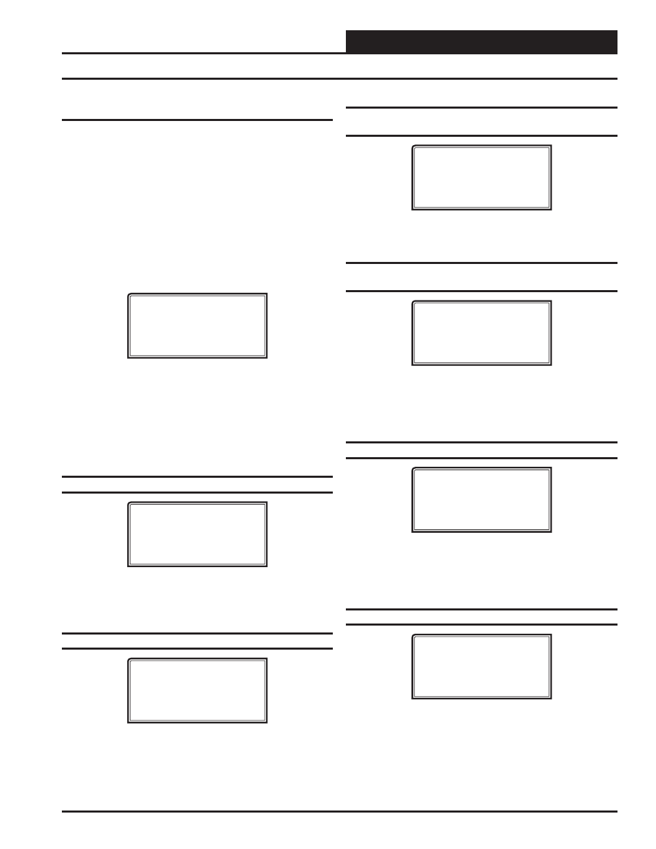
1) Change Setpoint
2) Configure Unit
3) Damper Force
ESC) Exit Menu
Press
<2>
on the keypad to enter the fi rst Unit Confi guration Screen.
Modular Service Tool Instructions
From any Menu Screen, press the
<Confi guration>
button. The Unit
Selection Screen will appear requesting that you enter the unit ID number.
Enter the correct unit ID number of the controller you want to confi gure
and press
<Enter>
. You will then see Unit Confi guration Screen #1.
Confi guration Screen #1 - System Type
Polling Unit Config
System Type
Selection: X
[0=Zoning 1=VAV]
This screen allows you to select whether you want the system to behave
as a VAV system or a Zoning System. If you select VAV, this will allow
tenant logging for your VAV system.
Confi guration Screen #2 - Last Polled Zone
Polling Unit Config
Last Polled Zone
Address: XX
[Enter Last Zone]
This zone is the last zone on the local loop of your zoning system that
is to be included in zone voting.
Confi guration Screen #3 - Mode Changeover
Time
Polling Unit Config
Mode Changeover Time
Minutes: XX
[Enter Period Time]
This is the amount of time that you want to allow between changeover
from heating to cooling modes.
Confi guration Screen #4 - Optimal Start
Target Zone
Polling Unit Config
Optimal Start
Target Zone..: XXX
[Enter Target Zone]
This is the unit ID of the Zone that you want to be satisfi ed by the
normally scheduled start time. If you enter “-1” into this box, it will
average all zones instead of picking a specifi c zone. If you do not require
Optimal Start, enter “0”.
Confi guration Screen #5 - Maverick Testing
Polling Unit Config
Maverick Testing
Disabled: YES
[0=NO 1=YES]
Disabling the Maverick Testing allows known troubled zone(s) to
continue voting without causing a Maverick alarm. In other words, all
zones are included in the voting regardless of whether they are more
than four degrees from setpoint.
Confi guration Screens #6-65 - Alarm Polling
Polling Unit Config
Enable Alarm Polling
Unit XX : YES
[0=NO 1=YES]
Enabling Alarm Polling allows any alarm from the loop to be polled.
You must set this for each controller on the loop.