Km a – Skutt KilnMaster Kilns Manufactured after March 1 2006 User Manual
Page 41
41
r
eplacing
the
therMOcOuple
eleMent
On
kM a
utOMatic
k
ilns
s
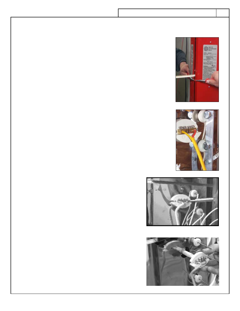
tep
1
Remove the screws that secure the red control box to the kiln.
●
s
tep
2
Swing the box open.
●
s
tep
3
The thermocouple has a yellow, insulated lead wire attached to the terminal
●
strip with slide on connectors and marked with positive (+) and negative (-).
n
Ote
: The negative (-) wire is red, not black!. Slide the connectors off the
terminal strip.
s
tep
4
Remove the two screws that hold the thermocouple terminal block onto the
●
heat shield.
s
tep
5
Gently pull the thermocouple assembly out of the brick.
●
s
tep
6
Loosen the two screws which hold the thermocouple element in place as
●
shown in the picture at right and remove it from the thermocouple block.
s
tep
7
Insert the new thermocouple element in place and tighten the screws.
●
s
tep
8
Reattach the terminal block onto the heat shield with the
●
two screws.
s
tep
9
Reconnect the thermocouple lead wire to the terminal strip,
●
matching the positive and negative markings.
s
tep
10
Close the box
●
k
iln
M
aster
c
OntrOller
c
ircuitry
The KilnMaster controller components are solid state and cannot
be repaired in the field. If repairs are necessary, call the factory at
503-774-6000 to arrange repairs.
D
O
nOt
senD
iteMs
WithOut
prOper
authOriZatiOn
.
R
ePaiRs