Tc type mv range chart – Super Systems 9205 Series User Manual
Page 122
Series 9205 Operations Manual Rev A
121
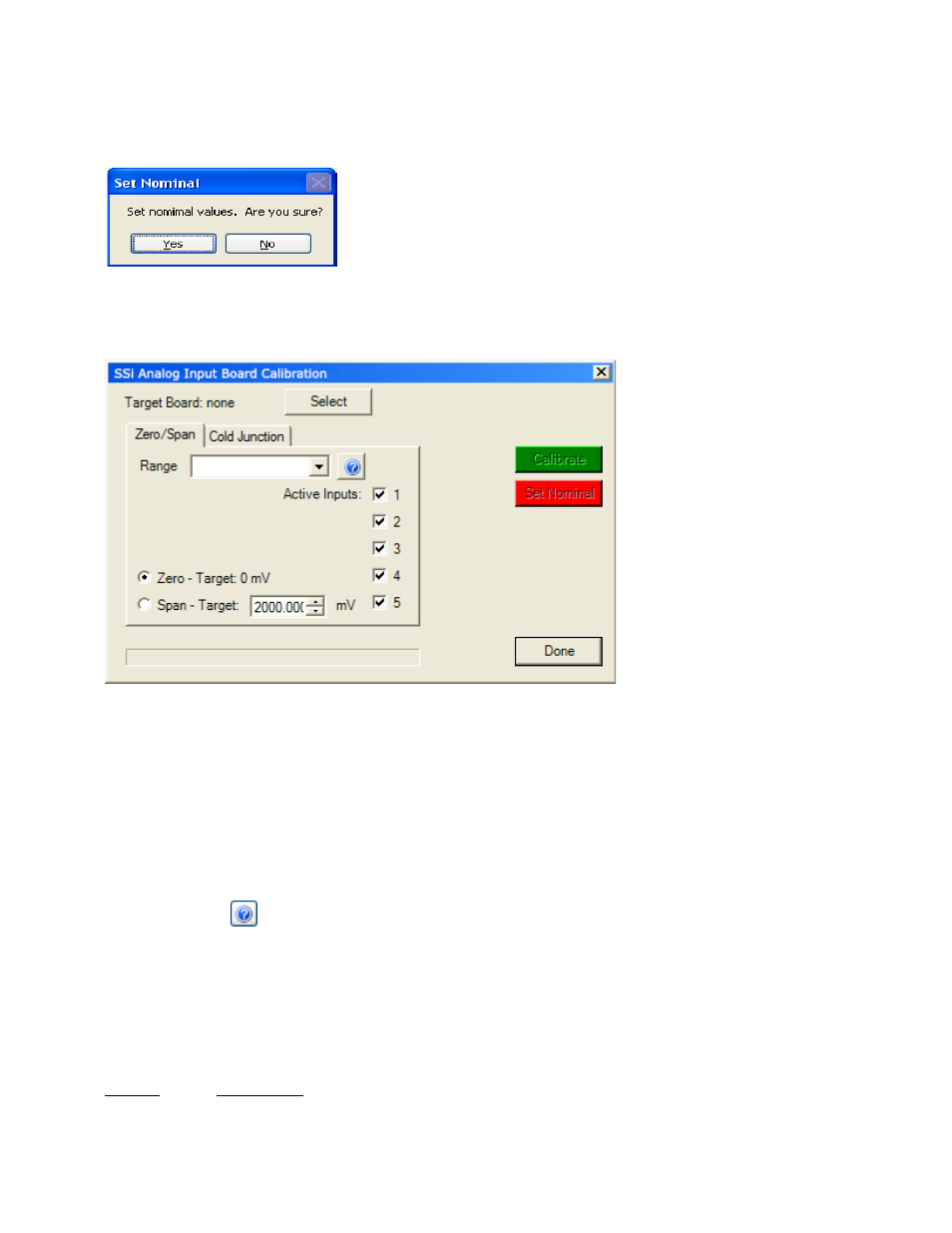
The
Calibration
screen for the Full Calibration menu option also has a Set Nominal button, which will set
nominal values for the current screen. The user will have to confirm the action.
Clicking on the Yes button will set the nominal values, and clicking on the No button will cancel the action.
Click the Done button to close the screen down.
Calibrate Aux Analog Input
If an SSi analog input board is
applicable, then this menu
option will be visible. The
Calibration menu screen will
allow the user to calibrate the
zero, span, and cold junction
trim value for all of the inputs
on each board.
The Select button will allow the
user to select one of the
current boards to calibrate.
Select the appropriate board
and click on the OK button.
Clicking on the Cancel button
will not select the board to
calibrate.
Note: A board must
be selected for calibration to
begin
.
The user will need a thermocouple calibrator capable of sourcing a thermocouple signal to calibrate the
zero, span or cold junction value. It is recommended to let everything (calibrator and datalogger) sit for
approximately thirty minutes to allow the temperature to achieve equilibrium. Set up the calibrator for the
specific thermocouple type, i.e. type K, type J, etc. Then, source a specific temperature, like 1000°F, or
millivolt to the connected input. It is recommended that the actual temperature used be similar to an
appropriate process temperature. For example, if your equipment normally operates at 1700°F, then
perform the cold junction calibration using a 1700 °F signal. It is important to note that when performing a
zero or span calibration,
do not use
regular thermocouple wiring. Instead, use any kind of regular sensor
wire, or even regular copper wire. To perform the calibrations, the user will need a calibrator that is
capable of outputting volts, millivolts, and temperature.
The “Zero/Span” tab will allow the user to perform a zero and span calibration on the selected board.
The help button -
- next to the “Range” drop-down list will allow the user to select a range based upon
an input type if the range is not known.
Select the input type and click on the OK button. The correct millivolt range will be displayed in the drop-
down list. Click on the Cancel button to cancel this action.
Below is a listing of the suggested ranges for the various TC types.
TC Type mV Range Chart
TC Type
Range in mV
B
20mV