Super Systems 9205 Series User Manual
Page 61
Series 9205 Operations Manual Rev A
60
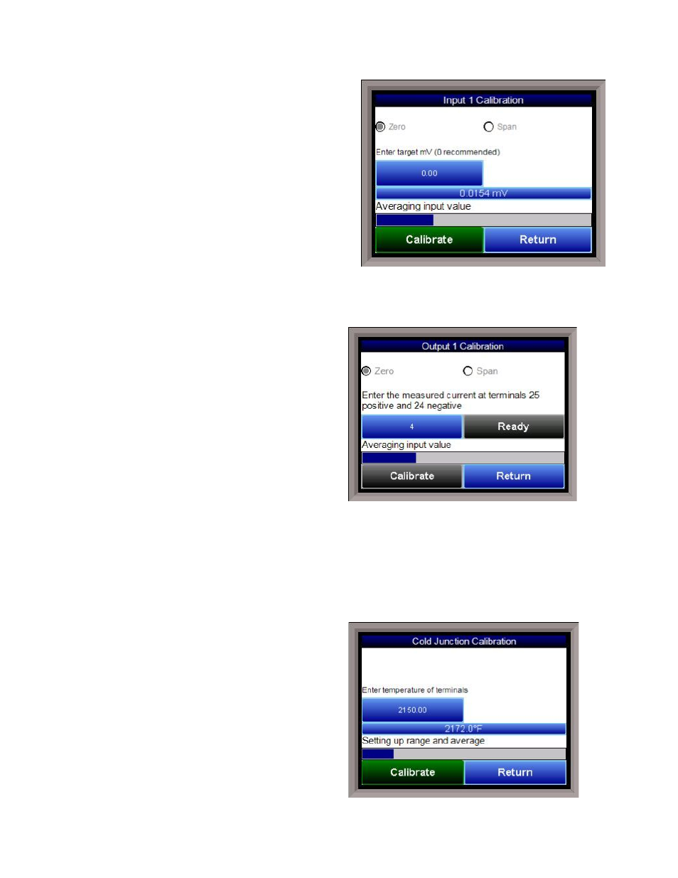
Zero Calibration - Inputs
To perform a zero calibration, click on the “Zero” option
- The circle will be filled in with a dot for the selected
option. For a zero calibration, the recommended value
to source is 0 mV.
Click on the Calibrate button to begin the calibration.
A progress bar will be displayed along the bottom of the
screen giving the progress of the calibration.
Span Calibration - Inputs
To perform a span calibration, click on the “Span”
option - The circle will be filled in with a dot for the
selected option. For a span calibration, the
recommended value is 90 % of the full range. For
example, if the range is 80 mV, then the span should be 72 mV. The recommended value can be changed by
clicking on the value, and entering the new value that way.
Click on the Calibrate button to begin the calibration.
A progress bar will be displayed along the bottom of the screen giving the progress of the calibration.
Zero Calibration - Outputs
To perform a zero calibration, click on the “Zero”
option - The circle will be filled in with a dot for the
selected option. When ready to start the calibration,
click on the Ready button. The user will then have to
measure the current at the appropriate output
terminals and enter that value on the button next to
the Ready button by clicking on that value button and
entering the value.
Click on the Calibrate button to begin the calibration.
A progress bar will be displayed along the bottom of
the screen giving the progress of the calibration.
Span Calibration - Outputs
To perform a span calibration, click on the “Span” option - The circle will be filled in with a dot for the
selected option. When ready to start the calibration, click on the Ready button. The user will then have to
measure the current at the appropriate output terminals and enter that value on the button next to the
Ready button by clicking on that value button and entering the value.
Click on the Calibrate button to begin the calibration.
A progress bar will be displayed along the bottom of the screen giving the progress of the calibration.
Cold Junction Calibration
The “Cold Junction” option will allow the user to
perform a cold junction trim on the selected board.
To determine if a cold junction adjustment is needed,
hook up the calibrator with the appropriate T/C wire
attached, and source a temperature to the input. It is
recommended to use an operating temperature to
source. For example, if the furnace typically runs at
1700 °F, then 1700 °F should be sourced to the input.
If the displayed value does not equal the value being
sourced, then a cold junction adjust would be
necessary. The “Offset” will be the amount of change
desired. For example, if 1700°F is being sourced, and
the “Value” is showing 1696.4 °F, then the “Offset”