Installing insulators and conductors – Allmand Brothers MB 6200 User Manual
Page 37
37
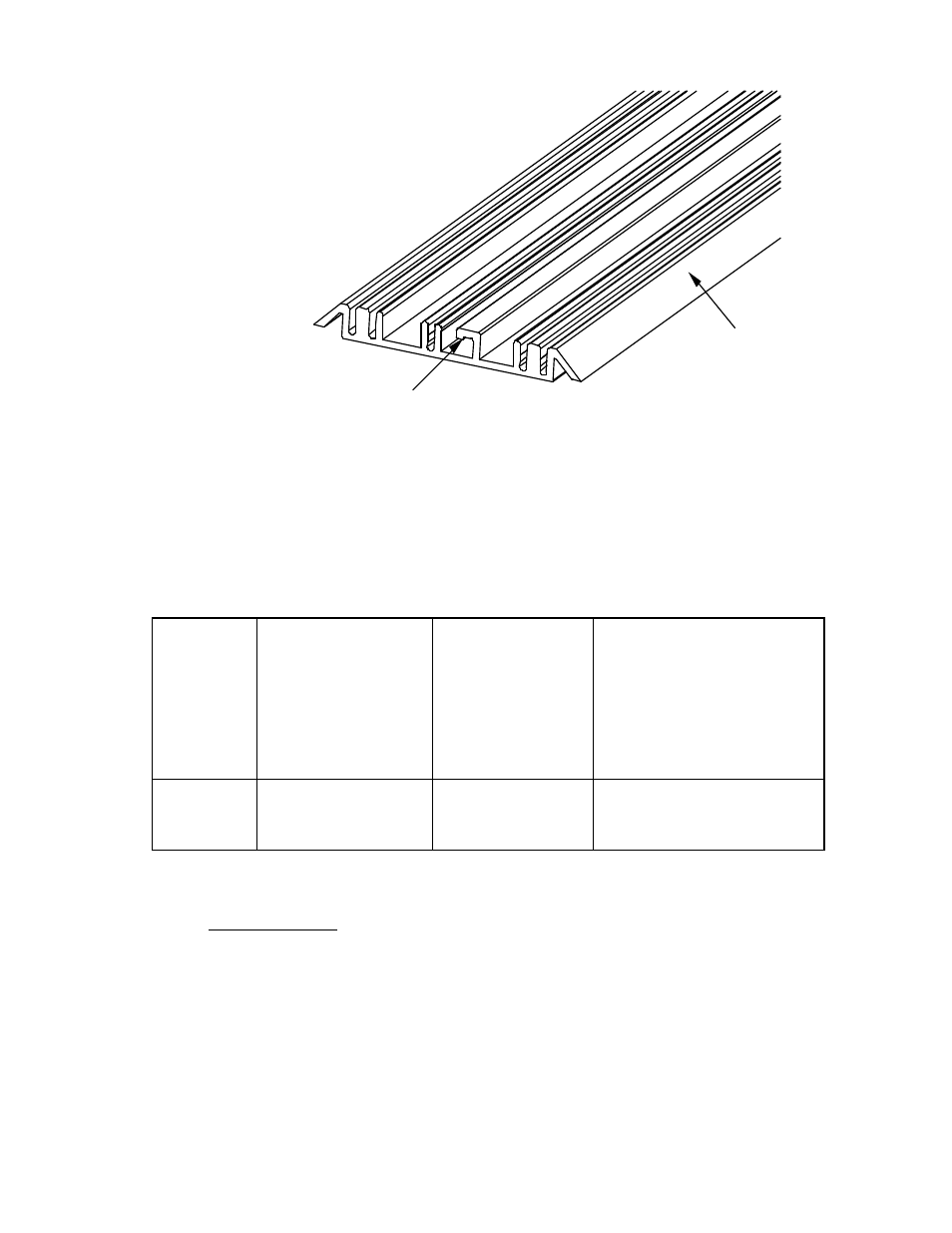
Figure 8. Rail (Left End Orientation)
Installing Insulators and Conductors
1. If the conductors are installed in the rail at the factory, verify that the reset conductor lengths are correct
for the proper BRICK configuration (see following table). If correct, skip to step 4.
2. Determine insulator (figure 9) and conductor (figures 10 and 11) lengths from the following table:
BRICK
Orientation
Insulator and Rail
Length
Power (+12 Vdc
and GND) and
Communications
Conductor Length
Reset Conductor Lengths
Horizontal
(Number of BRICKs
×
19.25 in. (4890 mm))
+
10 in. (2540 mm)
1/2-inch (130 mm)
shorter than insulator
Starting =
18.25 in. (4635 mm)
Interior =
17.25 in. (4380 mm)
Ending =
8.25 in. (2095 mm)
Vertical
(Number of BRICKs
×
13.75 in. (3490 mm))
+
10 in. (2540 mm)
1/2-inch (130 mm)
shorter than insulator
Starting =
13.25 in. (3365 mm)
Interior =
11.75 in. (2980 mm)
Ending =
8.00 in. (2030 mm)
3. Cut to proper length.
4. Press the conductor insulator into grooves 1, 3, 4 and 5 (see figure 9). The left edge of the rail is deter-
mined by the orientation of the Locking Flange—see figure 8.
Rail
Locking Flange