Allmand Brothers MB 6200 User Manual
Page 39
39
5. The conductor should start indented 1/4-inch (64 mm) from the left edge of the rail (the left edge of the
rail is determined by the orientation of the Locking Flange—see figure 8). When completed, the conduc-
tor should be indented 1/4-inch (64 mm) at both edges of the rail. Working from left to right, in groove 1,
press and tap in (with rubber mallet) the communications conductor into the conductor insulator until fully
seated (see figure 10).
6. For grooves 3 and 5, repeat step 5 (see figures 9 and 10).
7. Starting at the left edge of groove 4, install the starting reset conductor as in step 5. The conductor
should start indented 1/4-inch (64 mm) from the end of the rail (see figure 11).
8. Insert the first reset conductor spacer into the insulator, butted tightly next to the starting reset conductor.
It is important that no gap is left between the reset conductors and the conductor spacers.
9. Butt an interior reset conductor tightly next to the reset conductor spacer. It is important that no gap is
left between the reset conductors and the conductor spacers.
10. Continue this process, alternating interior reset conductors and reset conductor spacers until complete,
finishing with the ending reset conductor. This conductor should be indented 1/4-inch (64 mm) from the
edge of the rail.
11. After all conductors have been installed per steps five through ten, check to make sure they are properly
seated in the rail assembly insulators.
12. Conductors should protrude approximately 0.50 in. (127 mm) above rail assembly. If the conductor is
more than 0.50 in. (127 mm) above rail assembly, gently tap in place using a rubber mallet.
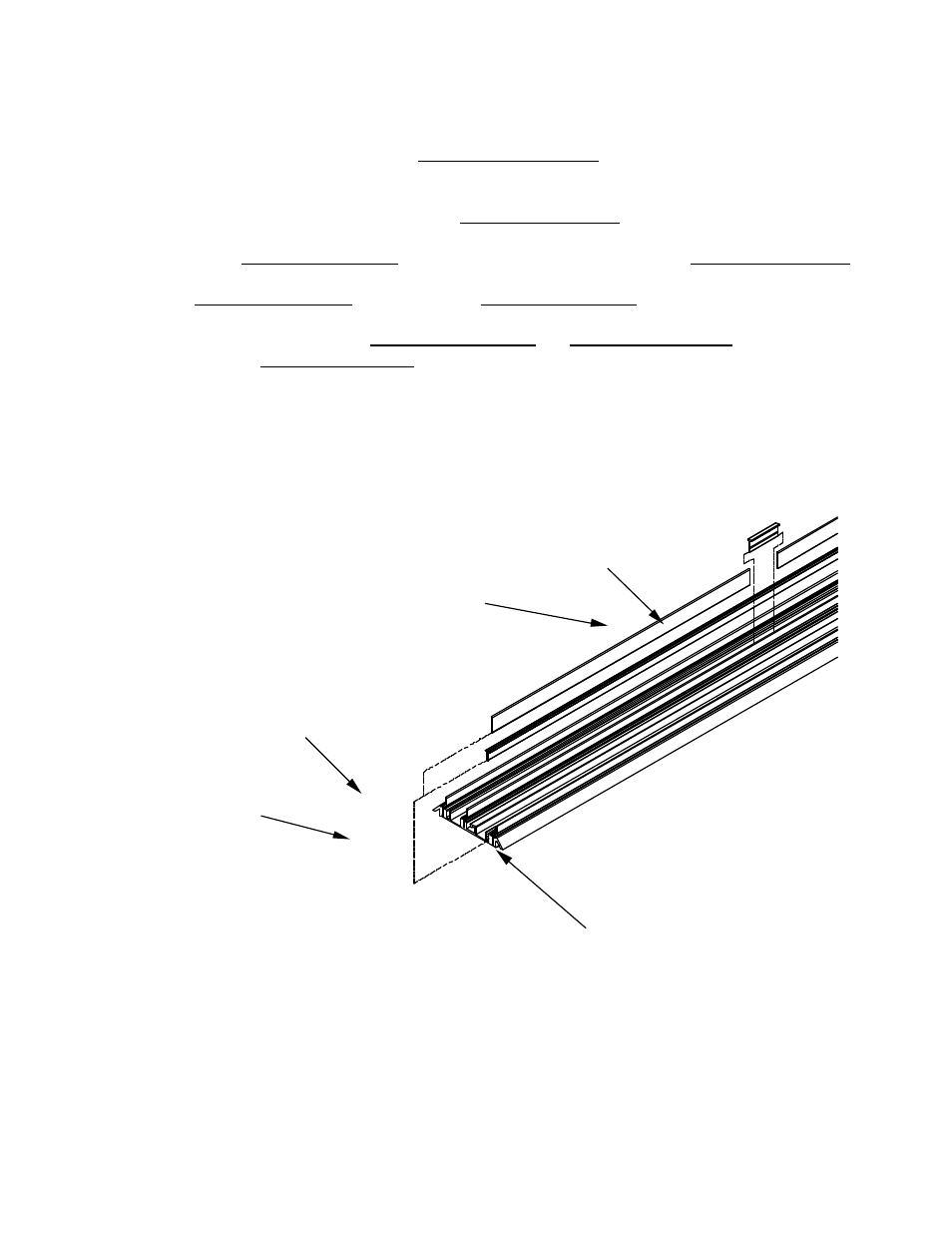
Figure 11. Complete Rail Assembly
Starting reset
conductor
Reset conductor
spacer
Insulator
Rail
Interior reset
conductor