Description and features – Allmand Brothers MB 6200 User Manual
Page 5
5
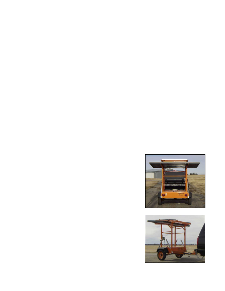
The trailer consists of a formed 10 GA steel deck with crossmembers and an integral battery
compartment with lockable cover. Four steel uprights welded to the deck support the sign panel
for operation and transportation. A positive mechanical lock secures the sign in both operating
and towing positions. The tongue is constructed of 3" structural steel channel and has a heavy-
duty combination 3" diameter pintle ring and 2" ball coupler. A folding screw jack is mounted to
the tongue immediately behind the pintle eye. Four adjustable corner stands (one at each corner
of the trailer) stabilize the trailer when in operation. They are constructed of 1-3/4" Telespar
tubing complete with footpads, locking pins, and clips. The trailer rides on a 1500 lb. tube-type
leaf spring axle with 5-lug hubs and 13" 4-ply rated tires and wheels. Raising and lowering of the
sign panel is accomplished by a ratchet-type hand crank winch and pulley system with safety
brake clutch and a single 3/16" braided steel cable that will raise and lower the sign panel
evenly. Flush mounted stop, turn, and taillights with a 4-contact male end connector on the cable
insures towing safety. Color coding of the wiring is in accordance with SAE practice, (SAE
J560A and SAE J895). The trailer is finished in high-visibility Safety Orange paint.
SAFETY AND PRECAUTIONS
A safe environment around the ALLMAND MESSAGE
BOARD is encouraged. The following recommendations
should be noted since the ALLMAND MESSAGE BOARD is
typically used in construction areas with greater traffic conges-
tion, thereby increasing the risk of accidents or injuries.
The sign panel should always be in travel position (lowered)
and secured using the attached lock pins when towing the
ALLMAND MESSAGE BOARD at highway speeds. Make
sure that the hitch is properly engaged with the towing vehicle
and that the safety chains are properly fastened and all jacks
and/or jackstands are raised and secured before towing. Also
be certain that the taillights are connected and working prop-
erly before towing the unit.
DESCRIPTION AND FEATURES
A low-voltage disconnect (LVD) system protects the batteries from damage if solar conditions fail
to adequately maintain a sufficient charge. This system features a red warning lamp which signals
low battery voltage and imminent shutdown of the system. This lamp is mounted on the rear of the
sign panel and is easily visible from the jobsite or roadway. If battery voltage becomes danger-
ously low, the red warning lamp will begin to flash. When voltage goes below an operative level,
the message board will shut down. At this time maintenance personnel will need to either re-
charge the batteries or replace them with fully charged units if necessary.