Attaching the rail assembly – Allmand Brothers MB 6200 User Manual
Page 40
40
Attaching the Rail Assembly
1. Before continuing, verify that the conductors are installed. See Installing Insulators and Conductors.
Caution
Do not make pre-drilled mounting holes in rail assemblies
larger. Drilling of additional holes is not recommended.
2. For rail assembly spacing, see following table:
BRICK Orientation
Rail Assembly Spacing Between Rows
Horizontal, Full Matrix
8.75 in. (2223 mm)—see figure 12 for spacing reference
Vertical, Full Matrix
14.25 in. (3620 mm)—see figure 12 for spacing reference
3. The mounting rail assembly must be supported approximately every
24 inches (6096 mm) on the side
mounting housing. The mounting rail assembly is pre-drilled every 4 inches (1020 mm) to accept 1/4-inch
(64 mm) bolts. These holes are slotted to allow for minor adjustments to the mounting rail assembly for
overall BRICK sign alignment. Always use appropriate fasteners (1/4-inch (64 mm) socket head bolts,
lock washers, nuts, sheet metal screws, or lag screws) for your mounting application.
4. Mount the lowest rail assembly with the reset conductor oriented towards the bottom edge. This will be
true for all Odd numbered rows (see figures 12 and 13).
5. Mount next highest rail assembly with the reset conductor oriented towards the top edge. This will be
true for all Even numbered rows (see figures 12 and 13). Also see in figure 13 the position of the slots,
which contain adjacent conductors, on the rail assembly.
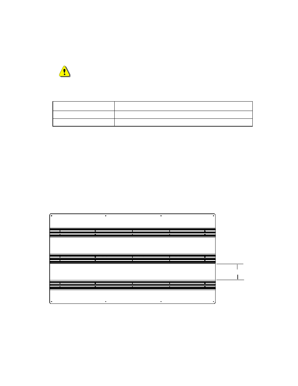
Figure 12. Full Matrix Sign—Mounting Rail Assemblies—Horizontal Orientation
rail spacing