Priority marking configuration example, Network requirements, Configuration procedure – H3C Technologies H3C S10500 Series Switches User Manual
Page 68
60
Card type
(right)
SC SE EA EB
QoS-local-I
D marking
Support
ed
Not
supporte
d
Support
ed
Not
supporte
d
Supporte
d
Not
supported
Supporte
d
Not
supported
Priority marking configuration example
Priority marking configuration example
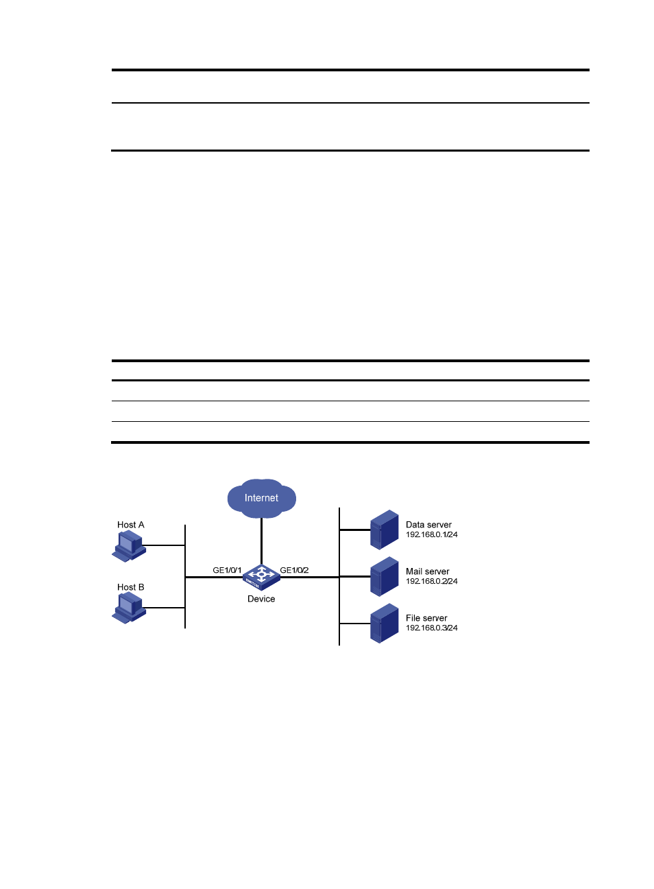
Network requirements
As shown in
, the company’s enterprise network interconnects hosts with servers through Device.
The network is described as follows:
•
Host A and Host B are connected to GigabitEthernet 1/0/1 of Device.
•
The data server, mail server, and file server are connected to GigabitEthernet 1/0/2 of Device.
Configure priority marking on Device to satisfy the following requirements:
Traffic source
Destination
Processing priority
Host A, B
Data server
High
Host A, B
Mail server
Medium
Host A, B
File server
Low
Figure 19 Network diagram for priority marking configuration
Configuration procedure
# Create advanced ACL 3000, and configure a rule to match packets with destination IP address
192.168.0.1.
<Device> system-view
[Device] acl number 3000
[Device-acl-adv-3000] rule permit ip destination 192.168.0.1 0
[Device-acl-adv-3000] quit
# Create advanced ACL 3001, and configure a rule to match packets with destination IP address
192.168.0.2.