Traffic redirecting configuration examples, Network requirements, Configuration procedure – H3C Technologies H3C S10500 Series Switches User Manual
Page 74: Example for redirecting traffic to the next hop
66
NOTE:
•
The actions of redirecting traffic to the CPU, redirecting traffic to an interface, and redirecting traffic to
the next hop are mutually exclusive with each other in the same traffic behavior.
•
A QoS policy with traffic redirecting actions can be applied to only the inbound direction of a port,
VLAN, or all ports.
•
When you configure IPv6 policy-based routing, the next hop IPv6 address in the traffic redirecting
action of the QoS policy cannot be a link-local address.
•
The default of the fail-action keyword is forward.
•
You can use the display traffic behavior user-defined command to view the traffic redirecting
configuration.
Traffic redirecting configuration examples
Example for redirecting traffic to the next hop
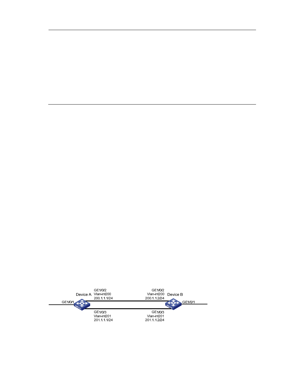
Network requirements
As shown in
, the network is described as follows:
•
Device A is connected to Device through two links. At the same time, Device A and Device B are
each connected to other devices.
•
GigabitEthernet 1/0/2 of Device A and GigabitEthernet 1/0/2 of Device B belong to VLAN 200.
•
Ethernet 1/3 of Device A and Ethernet 1/3 of Device B belong to VLAN 201.
•
On Device A, the IP address of VLAN-interface 200 is 200.1.1.1/24, and that of VLAN-interface
201 is 201.1.1.1/24.
•
On Device B, the IP address of VLAN-interface 200 is 200.1.1.2/24, and that of VLAN-interface
201 is 201.1.1.2/24.
Configure the actions of redirecting traffic to the next hop to implement policy-based routing and satisfy
the following requirements:
•
Packets with source IP address 2.1.1.1 received on GigabitEthernet 1/0/1 of Device A are
forwarded to IP address 200.1.1.2.
•
Packets with source IP address 2.1.1.2 received on GigabitEthernet 1/0/1 of Device A are
forwarded to IP address 201.1.1.2.
•
Other packets received on Ethernet 1/1 of Device A are forwarded according to the routing table.
Figure 21 Network diagram for redirecting traffic to the next hop
Configuration procedure
# Create basic ACL 2000, and configure a rule to match packets with source IP address 2.1.1.1.
<DeviceA> system-view