Network requirements, Configuration procedure, Qppb configuration example in an mpls l3vpn – H3C Technologies H3C S10500 Series Switches User Manual
Page 85
77
[DeviceB] qos policy qppb
[DeviceB-qospolicy-qppb] classifier qppb behavior qppb mode qppb-manipulation
[DeviceB-qospolicy-qppb] quit
# Apply the QoS policy to the incoming traffic of VLAN 4.
[DeviceB] qos vlan-policy qppb vlan 4 inbound
4.
Verify the configuration
# Check whether the related route on Device B takes effect.
[DeviceB] display ip routing-table 1.1.1.0 24 verbose
Routing Table : Public
Summary Count : 1
Destination: 1.1.1.0/24
Protocol: BGP Process ID: 0
Preference: 255 Cost: 0
IpPrecedence: QosLcId: 3
NextHop: 168.1.1.1 Interface: Vlan-interface3
BkNextHop: 0.0.0.0 BkInterface:
RelyNextHop: 0.0.0.0 Neighbor : 168.1.1.1
Tunnel ID: 0x0 Label: NULL
State: Active Adv GotQ Age: 00h00m45s
Tag: 0
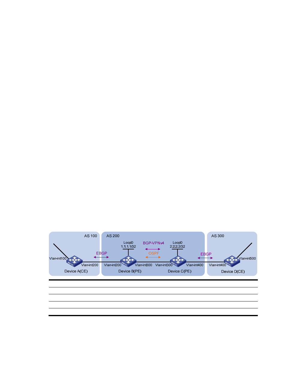
QPPB configuration example in an MPLS L3VPN
Network requirements
As shown in
, all switches run BGP. Device C receives routes, sets the QPPB IP precedence and
QoS-local IDs, and uses the QoS policy to limit the traffic rate to 512 kbps.
Figure 25 Network diagram for QPPB configuration in an MPLS L3VPN
Device Interface IP
address
Device Interface IP
address
Device A
Vlan-int100
192.168.1.2/24
Device B
Vlan-int200
167.1.1.2/24
Vlan-int200 167.1.1.1/24
Vlan-int300 168.1.1.2/24
Device C
Vlan-int400
169.1.1.2/24
Device D
Vlan-int400
169.1.1.1/24
Vlan-int300 168.1.1.1/24
Vlan-int500 192.168.2.2/24
Configuration procedure
1.
Configure IP addresses for each interface (omitted)
2.
Configure Device A
# Configure a BGP connection.