HEIDENHAIN MANUALplus 4110 Pilot User Manual
Page 110
110
Lathe tools
WO = 1
WO = 7
Z
Z
X
X
B
B
A
A
R
R
Lathe tools
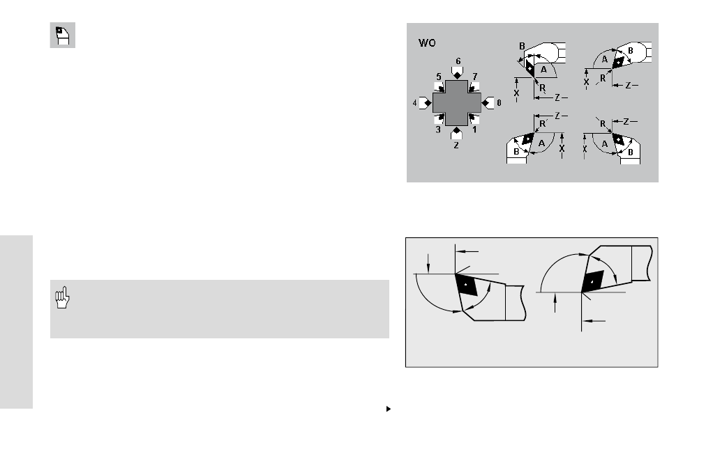
Tool parameters
X, Z:
Setup dimensions
R:
Cutting radius
WO:
Tool orientation (number shown in graphic support window)
A:
Setup angle – range: 0°
A 180°
B:
Tip angle – range: 0°
B 180°
DX, DZ: Wear compensation
Q:
(Reference to) tool text
MD:
Direction of rotation (3=M3; 4=M4) default: not assigned
TS:
Cutting speed – default: not defined
TF:
Feed rate – default: not defined
PT:
Tool life – default: not defined
RT:
Rem. dwell: Remaining tool life (display field)
PZ:
Number of units – default: not defined
RZ:
Remaining pieces (display field)
The direction of the setup angle depends on the tool orienta-
tion. The figure at top right illustrates how goose-necked
roughing or finishing tools for longitudinal machining with
WO= 1, 3, 5, 7 are dimensioned.
Facing tools
Facing tools are defined in the same way as those for longitudinal
turning. The figure below explains the dimensioning of facing tools
with tool orientation WO=1 and WO=7.
Continued