HEIDENHAIN MANUALplus 4110 Pilot User Manual
Page 114
114
Dr
illing t
ools
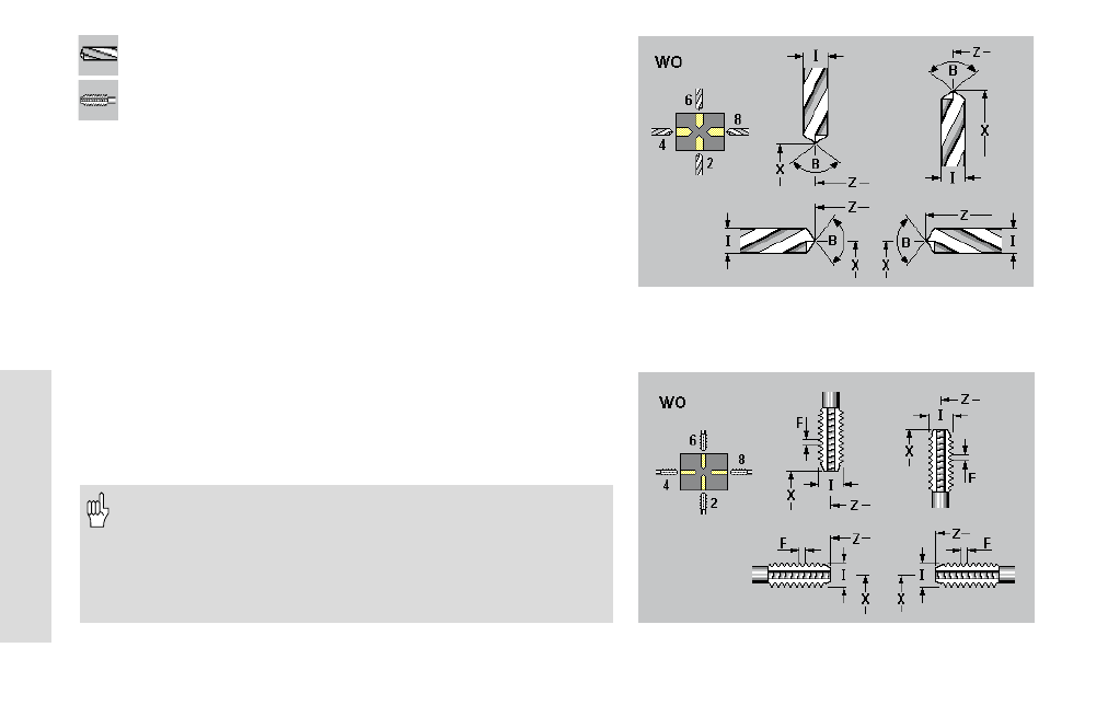
Drilling tools
Tapping tools
Tool parameters
X, Z:
Setup dimensions
WO:
Tool orientation (number shown in graphic support window)
I:
Hole diameter / thread diameter
B:
Tip angle – range: 0°<B
180°
F:
Thread pitch
DX/DZ:
Wear compensation
H:
Tool driven (0=not driven; 1=driven) default: 0
Q:
(Reference to) tool text
MD:
Direction of rotation (3=M3; 4=M4) default: not assigned
TS:
Cutting speed – default: not defined
TF:
Feed rate – default: not defined
PT:
Tool life – default: not defined
RT:
Rem. dwell: Remaining tool life (display field)
PZ:
Number of units – default: not defined
RZ:
Remaining pieces (display field)
Drilling tools
• When drilling with“constant cutting speed“, MANUALplus
calculates the spindle speed from the “hole diameter I“.
• I and B are necessary to show the tool tip in graphic simulation.
Tapping tools: “F“ is evaluated if the thread pitch parameter
is not defined in the tapping cycle.
Drilling tools
Tapping tools