SMA SB 1.5-1VL-40 User Manual
Page 17
Advertising
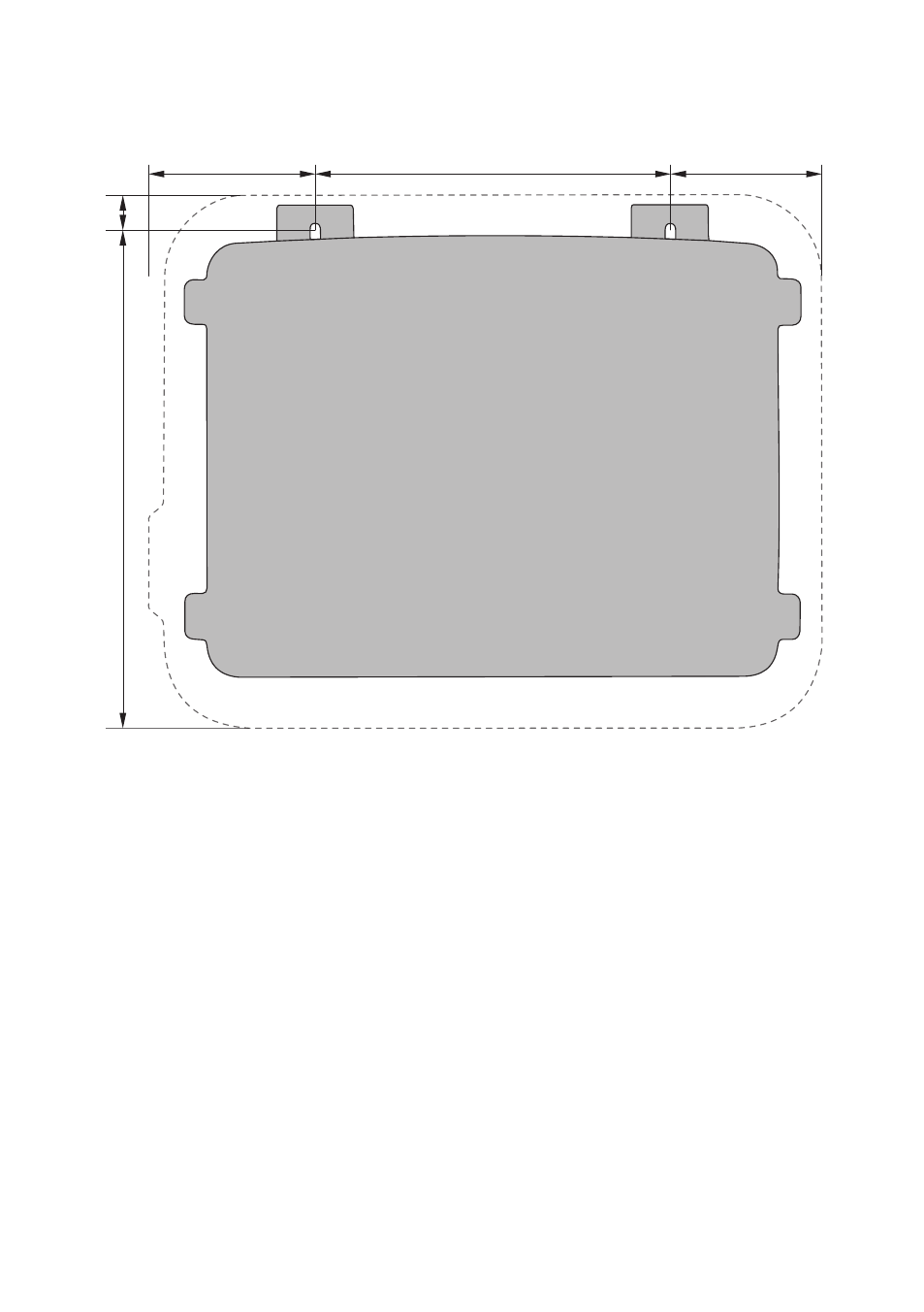
Dimensions for mounting:
115 mm
105 mm
240 mm
334 mm
23
mm
Figure 3: Position of the anchoring points
Recommended clearances:
If you maintain the recommended clearances, adequate heat dissipation will be ensured. Thus, you
will prevent power reduction due to excessive temperature.
☐ Maintain the recommended clearances to walls as well as to other inverters or objects.
☐ If multiple inverters are mounted in areas with high ambient temperatures, increase the
clearances between the inverters and ensure sufficient fresh-air supply.
5 Mounting
SMA Solar Technology AG
Operating Manual
17
SB15-25-BE-en-10
Advertising
This manual is related to the following products: