4 connecting the inverter to the network, Connecting the inverter to the network – SMA SB 1.5-1VL-40 User Manual
Page 26
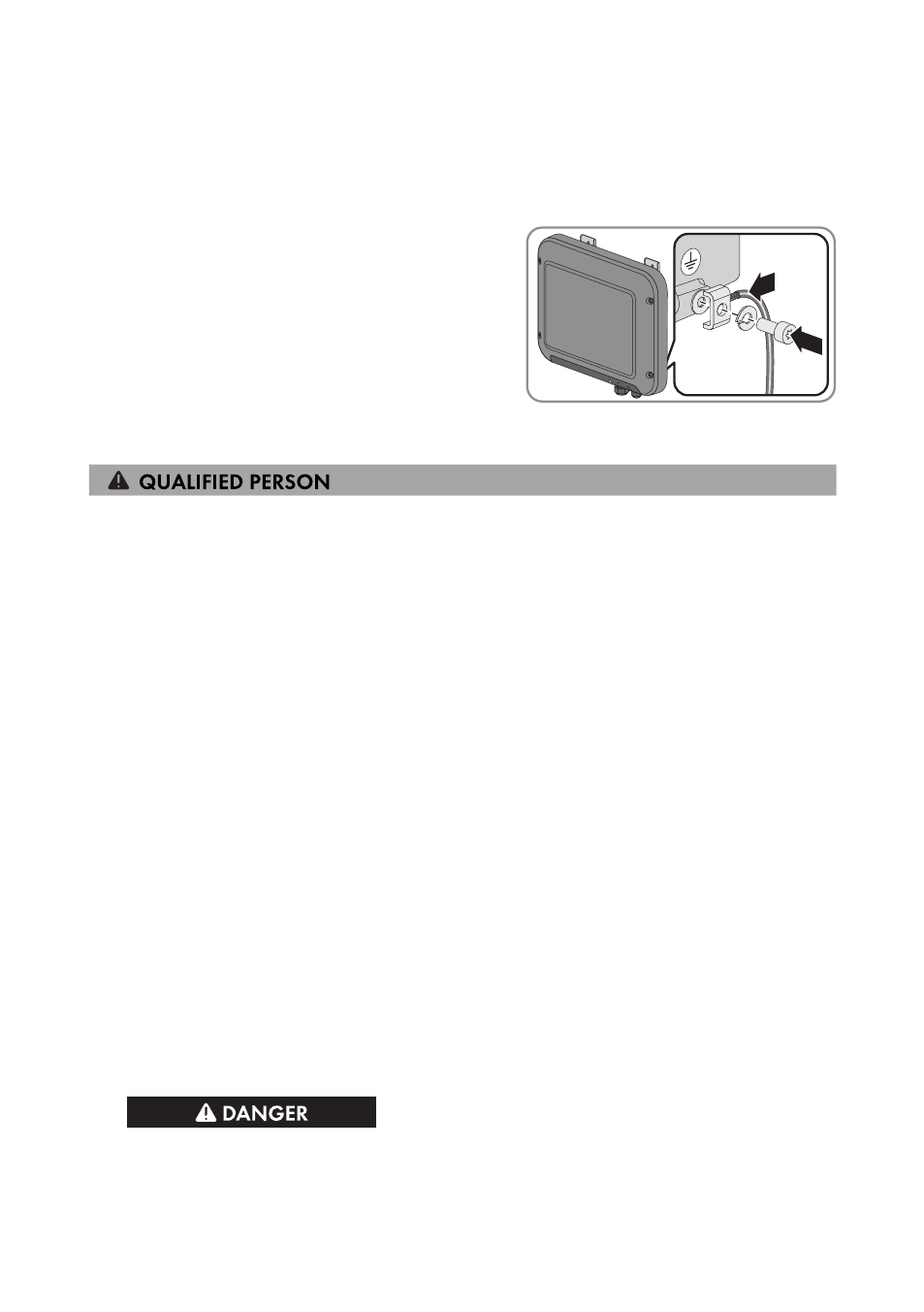
Procedure:
1. Strip off 12 mm of the grounding cable insulation.
2. Thread the screw through the spring lock washer, the clamping bracket and the washer.
3. Screw the screw into the thread slightly.
4. Lead the grounding cable between the washer
and clamping bracket and tighten the screw
(torque: 6 Nm) using a Torx screwdriver (TX25).
6.4
Connecting the Inverter to the Network
Additionally required material (not included in the scope of delivery):
☐ One network cable
☐ Where required: Field-assembly RJ45 connector. SMA Solar Technology AG recommends the
connector "MFP8 T568 A Cat.6A" from "Telegärtner".
☐ When laying the network cable outdoors: Overvoltage protection of the installation between
the network cable from the inverter and the local network in the building. The overvoltage
protection prevents overvoltages from being conducted via the network cable into the building
and to other network devices in the event of a lightning strike.
Cable requirements:
The cable length and quality affect the quality of the signal. Observe the following cable
requirements.
☐ Cable type: 100BaseTx
☐ Cable category: Cat5, Cat5e, Cat6, Cat6a or Cat7
☐ Plug type: RJ45 of Cat5, Cat5e, Cat6 or Cat6a
☐ Shielding: SF/UTP, S/UTP, SF/FTP or S/FTP
☐ Number of insulated conductor pairs and insulated conductor cross-section: at least
2 x 2 x 0.22 mm²
☐ Maximum cable length between two nodes when using patch cables: 50 m
☐ Maximum cable length between two nodes with installation cable: 100 m
☐ UV-resistant for outdoor use
Procedure:
1.
Danger to life due to electric shock
• If the inverter is already in operation, disconnect the inverter from voltage sources (see
6 Electrical Connection
SMA Solar Technology AG
Operating Manual
SB15-25-BE-en-10
26