3 connecting additional grounding, Connecting additional grounding – SMA SB 1.5-1VL-40 User Manual
Page 25
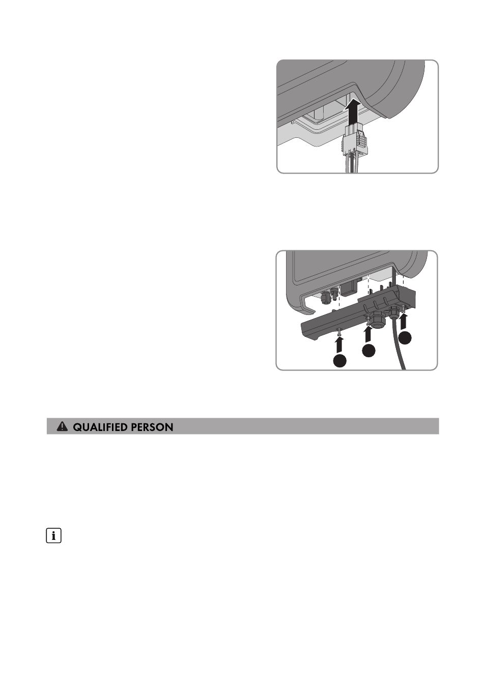
10. Plug the AC connector into the pin connector in
the inverter until it snaps into place.
11. Check to ensure that the AC connector is securely in place by pulling lightly on the AC
connector.
12. Tighten the swivel nut slightly.
13. If you would like to integrate the inverter into a local network via Ethernet, connect the inverter
now (see Section 6.4, page 26).
14. Attach the connection cap to the inverter using
the three screws and a Torx screwdriver (TX20)
(torque: 3.5 Nm).
1
2
3
15. Tighten the swivel nut hand-tight.
6.3.3
Connecting Additional Grounding
If additional grounding or equipotential bonding is required locally, you can connect additional
grounding to the inverter. This prevents touch current if the grounding conductor at the terminal for
the AC cable fails.
The required clamping bracket, the cylindrical screw M5x16, the washer and the spring lock
washer are part of the scope of delivery of the inverter.
Cable requirements:
Use of fine-stranded conductors
You can use an inflexible or a flexible, fine-stranded conductor.
• When using a fine-stranded conductor, it has to be double crimped by a ring terminal lug.
Make sure that no insulated conductor is visible when pulling or bending. This will ensure
sufficient strain relief by means of the ring terminal lug.
☐ Grounding cable cross-section: max. 10 mm²
6 Electrical Connection
SMA Solar Technology AG
Operating Manual
25
SB15-25-BE-en-10