SMA SB 1.5-1VL-40 User Manual
Page 32
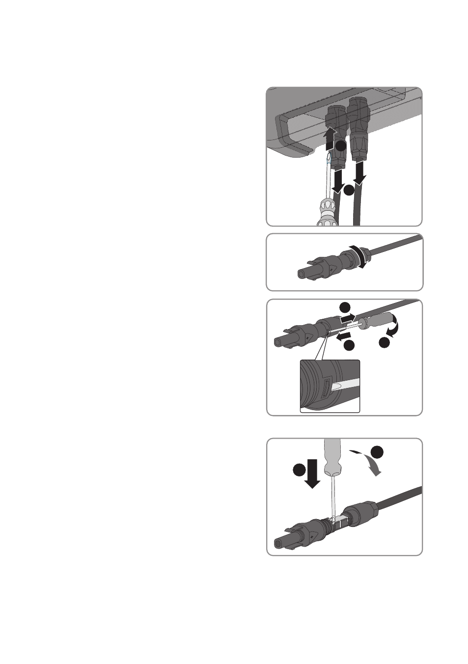
Procedure:
1. Set the DC load-break switch of the inverter to position O.
2. Release and remove all DC connectors. To do
this, insert a flat-blade screwdriver or an angled
screwdriver (blade width 3.5 mm) into one of
the slide slots and pull the DC connectors out in
a downward direction. Do not pull on the cable.
1
2
3. Remove the DC connector swivel nut.
+
4. Unlock the DC connector. To do this, insert a flat-
blade screwdriver (blade width: 3.5 mm) into
the side catch mechanism and pry the catch
mechanism open.
+
1
2
3
5. Carefully pull the DC connector apart.
6. Release the clamping bracket. To do so, insert a
flat-blade screwdriver (blade width: 3.5 mm) into
the clamping bracket and pry the clamping
bracket open.
+
1
2
7. Remove the cable.
6 Electrical Connection
SMA Solar Technology AG
Operating Manual
SB15-25-BE-en-10
32