6 connecting the dc cable, Connecting the dc cable – SMA SC 400HE Installation User Manual
Page 76
External Connections
SMA Solar Technology AG
76
SCxxxHE-IEN104432
Installation Guide
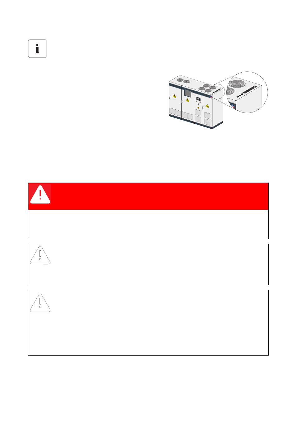
9. Feed the cables through the cable glands in the
roof of the AC cabinet to the internal power supply
transformer.
10. The power supply is fed from the secondary side of
the internal power supply transformer to the
terminals in the Sunny Central, see
6.5.1 ”Connecting the External Power Supply”
(page 72).
6.6 Connecting the DC Cable
Optional low-voltage HRC fuses are located in the DC cabinet of the Sunny Central, allowing the
connection of string distribution boxes. All Sunny Central inverters are equipped as standard with one
busbar per potential.
Connection of aluminum terminal lug
If aluminum terminal lugs are used for connection to the copper bar, refer to notes in
chapter 6.1 ”Connecting High-Current Contacts” (page 50).
DANGER!
Death or serious injuries. Risk of electric shock when touching the DC cable
attached to the PV generator.
• Cover the PV modules.
• Follow all safety instructions of the module manufacturer.
• Disconnect the Sunny Central.
NOTICE!
Damage to the Sunny Central or the PV generator due to faulty DC cabling
• When connecting the DC cables, it is obligatory to follow the circuit diagram
provided.
NOTICE!
Weak voltage resistance or poor sealing could impair operational capacity.
• Ensure that the DC cables are appropriately voltage-resistant!
• Lay the DC cables so that they are ground- and short-circuit-proof.
• All cable inlets must be sealed airtight with respect to the local environment. This
prevents cooling air from being sucked into the system bypassing the inlet filters.
SMA
SUNNY C
ENTRAL 63
0HE