1 connecting the dc cable to the busbar, Connecting the dc cable to the busbar – SMA SC 400HE Installation User Manual
Page 77
SMA Solar Technology AG
External Connections
Installation Guide
SCxxxHE-IEN104432
77
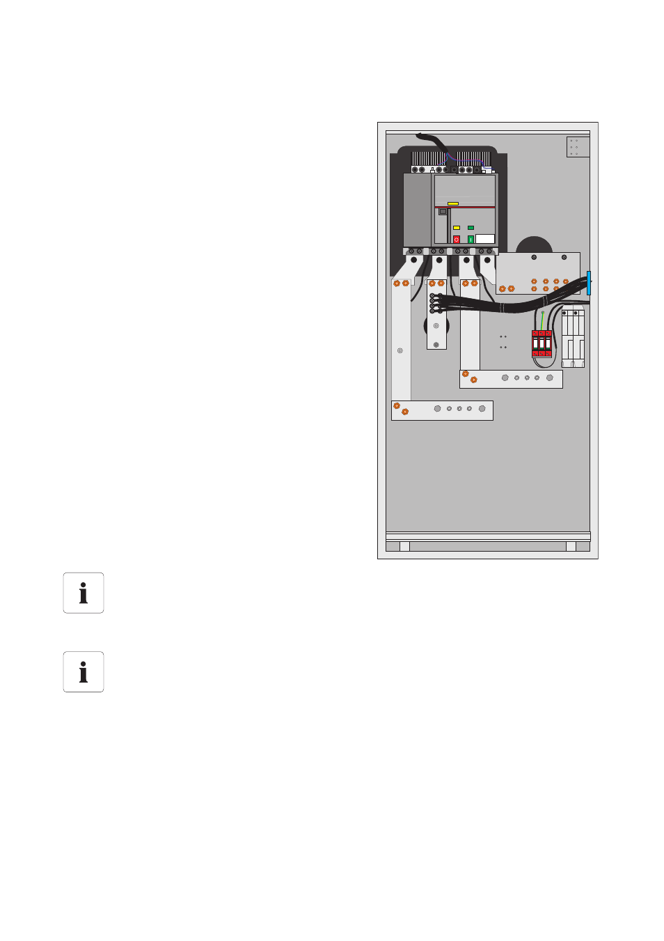
6.6.1 Connecting the DC Cable to the Busbar
1. Remove the narrow sliding plate located in the rear part of the DC cabinet.
2. Attach the sealing tape to the rear frame of the base.
3. Pull the DC cables into the interior of the switch cabinet and cut them to length up to the busbars.
4. For strain relief, use cable clips to fasten the cables to the cable rail.
5. Attach the sealing tape to the front side of the narrow sliding plate.
6. Insert the narrow sliding plate against the mounted DC cables.
7. If necessary, seal the free space around the cable inlet using PU foam.
The cables are fed through the base and floor of the DC
cabinet. The DC cables can be connected to 3
connection points wit the DC busbar. In total, 6 cables
each with 300 mm² per potential can be connected to
the busbars.
Mounting material for the connection
The mounting material is installed to the bar in the factory. A M12 ring terminal lug is used
for the connection to the bar and must be provided for by the customer.
Connecting the terminal lugs to the DC busbar
Do not connect the terminal lugs one on top of the other, rather connect them to the DC
busbar from the front and back.
L-
L+
L+
L-
L-
L+