8 remote deactivation unit, Remote deactivation unit – SMA SC 400HE Installation User Manual
Page 86
External Connections
SMA Solar Technology AG
86
SCxxxHE-IEN104432
Installation Guide
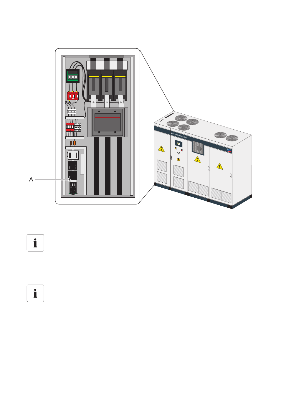
Shield bus (A) in the area of the external connection terminals in the Sunny Central
6.8 Remote Deactivation Unit
In addition to the key switch, another deactivation device can be implemented. It is installed on the
terminals in the Sunny Central. For this purpose, a 230 V power supply must be connected with the
internal terminal.
Cable routing of the remote deactivation unit
The cable is fed in through the sliding plate in the floor of the AC cabinet.
Remote deactivation unit
For special project-specific requirements, the Sunny Central can be fitted with a remote
deactivation unit combined with monitoring of the activation condition. This switching
option allows the Sunny Central to be controlled from a control center without activating
the key switch on the Sunny Central.
When connecting the remote deactivation unit, the circuit diagram included must be
observed.