3 overview of the analog inputs, 4 handling the shield contact – SMA SC 400HE Installation User Manual
Page 85
SMA Solar Technology AG
External Connections
Installation Guide
SCxxxHE-IEN104432
85
6.7.3 Overview of the Analog Inputs
If you use sensors other than those listed here, contact the SMA Serviceline.
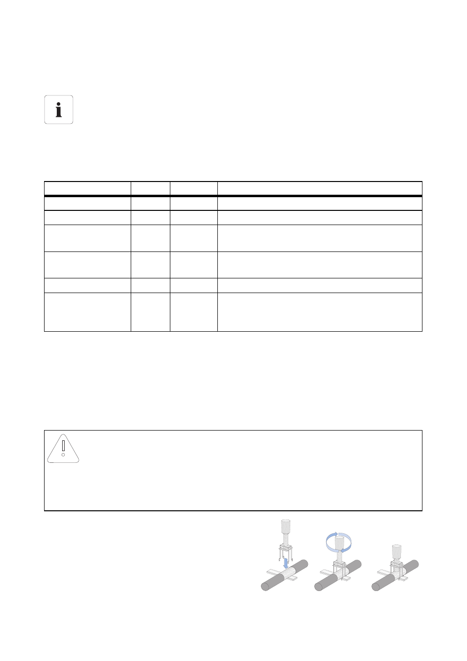
6.7.4 Handling the Shield Contact
The external signal and bus cables must be shielded. The shield must contact the shield bus, provided
for this purpose, along a large surface area.
The contact is made with the shield clamps included in the delivery.
Assignment of the analog inputs on the Sunny Central Control
When connecting the analog inputs and for the digital signals, it is obligatory to follow the
circuit diagram included with delivery.
The connection is made at the connection terminals. Here, the connections for
four‑conductor and two-conductor sensors should be noted and any required measuring
converters should be made available.
Analog inputs
Ain
Name
Meaning
Customer
Ain1
ExtSolP
External default nominal value for active power
Customer
Ain3
ExtSollrr
External radiation sensor
Customer
Ain4
ExtGlolrr
Pyranometer (measurement of global solar
irradiation)
Customer
Ain5
ExtAlarm
External alarm input, e.g. for monitoring the
functioning of the medium-voltage transformer
Customer
Ain6
ExtSolQ
External default nominal value for reactive power
Customer
Ain8
TmpExt C External temperature sensor / PT 100From
production version "C", this PT 100 is installed as
standard at the factory.
NOTICE!
The shield clamps could become damaged through improper handling
• The shield clamps must only be hand-tightened. Never use a screwdriver.
• Tightening the clamps with the use of a screwdriver can damage the insulation of the
individual insulated conductors in the cable.
The correct handling of the shield clamps is shown in
the figure on the right.