6 main control pcb comparison – Yaskawa GPD515/G5 User Manual
Page 12
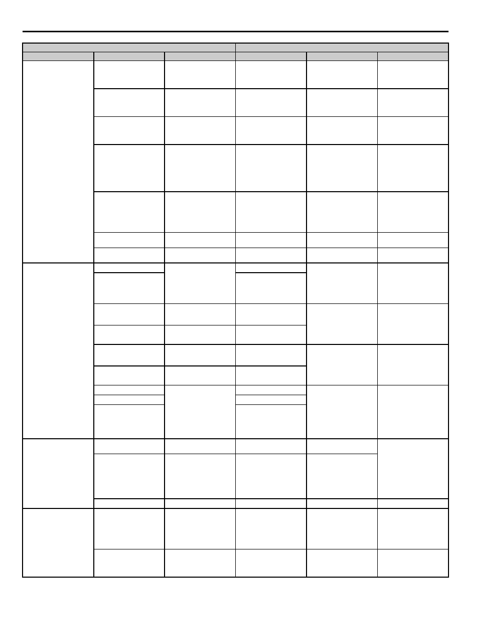
6 Main Control PCB Comparison
12
YASKAWA PL.A1000.01 G5 to A1000 - Product Transition Guide
Analog Input Signal
15
+15 V Power supply output
for analog command
(Allowable current 20 mA
maximum)
+V
+10.5 Vdc power output
+10.5 Vdc
(Maximum Current: 20mA)
33
-15V Power supply output
for analog command
(Allowable current 20mA
maximum)
-V
-10.5Vdc power output
-10.5Vdc (Maximum
Current: 20 mA)
13
Master frequency ref.
(voltage)
-10 to +10 V (20 kΩ)
0 to +10V (20 kΩ)
A1
Multi-function analog input
1 (Frequency reference bias)
-10 to 10 Vdc, 0 to 10 Vdc
(Input impedance: 20 kΩ)
14
Master frequency ref.
(current)
4 to 20 mA (250 Ω)
A2
Multi-function analog input
2 (Frequency reference bias)
-10 to 10 Vdc, 0 to 10 Vdc
(Input impedance: 20 kΩ)
4 to 20 mA, 0 to 20 mA
(Input impedance: 250 kΩ)
(Voltage or current input
must be selected by DIP
switch S1 and H3-09)
16
Multi-function analog input
-10 to +10 V (20 kΩ),
0 to +10 V (20 kΩ)
A3
Multi-function analog input
3 (Auxiliary frequency
reference), PTC input
-10 to 10 Vdc, 0 to 10 Vdc
(input impedance: 20 kΩ)
Use DIP switch S4 on the
terminal board to select
between analog and PTC
input.
17
Common for control circuit
0 V
AC
Analog frequency reference
common
0 V
12
Connection to shield sheath
of signal lead
E(G)
Shield wire, optional ground
line connection point
–
Digital Output Signals
9
During running (NO contact)
Dry contact capacity:
250 Vac, 1 A or less 30 Vdc,
1 A or less
M1
During run
(N.O. contact)
Form A dry contact capacity:
1 A maximum at 250 Vac
1 A maximum at 30 Vdc
Multi-function digital output.
Function set by H2-01.
10
M2
25
Zero speed detection
Open collector output
48 V, 50 mA or less
M3
Zero speed
(N.O. contact)
Form A dry contact capacity:
1 A maximum at 250 Vac
1 A maximum at 30 Vdc
Multi-function digital output.
Function set by H2-02.
27
Open collector output
common
M4
26
Speed agree detection
Open collector output
48 V, 50 mA or less
M5
Frequency agree
(N.O. contact)
Form A Dry contacts
capacity:
1 A maximum at 250 Vac
1 A maximum at 30 Vdc
Multi-function digital output.
Function set by H2-03.
27
Open collector output
common
M6
18
Fault contact output
(NO/NC contact)
When faulted : Closed
between terminals 18 and 20,
Open between terminals 19
and 20. Dry contact
capacity: 250 Vac 1 A or
less, 30 V 1 A or less
MA
Fault output signal
(SPDT)
Form C dry contact capacity:
1 A maximum at 250 Vac
1 A maximum at 30 Vdc
19
MB
20
MC
Analog Output Signals
21
Frequency meter output
0 to 10 V, 2 mA or less
FM
Output frequency
(Multi-function)
0 to +10 Vdc or
+/-10 Vdc 500 ohm input
10 V=100 %
Output frequency
(Maximum current 2 mA).
4 to 20 mA
20 mA = 100 %
Output frequency,
Function set by H4-01.
23
Current monitor
5 V = inverter rated current,
2 mA or less
AM
Output current
(Multi-function)
22
Common (Current Monitor)
AC
Analog common
–
Pulse I/O
—
—
RP
Pulse input
0 to 32 kHz (3 kΩ) ±5 %
High level voltages 3.5 to
13.2
Low level voltages 0.0 to 0.8
Duty Cycle (on/off) 30 % to
70 %, function set by H6-01.
—
—
MP
Pulse monitor
0 to 32 kHz
+5 V output
(Load: 1.5 kΩ)
Function set by H6-06.
GPD515/G5 Terminal
A1000 Terminal (Designations similar to GPD515/G5)
Type
GPD515/G5 Terminal
Default Functions
A1000 Terminal
Default Function
A1000 Description