10 appendix 2 parameter cross reference – Yaskawa GPD515/G5 User Manual
Page 44
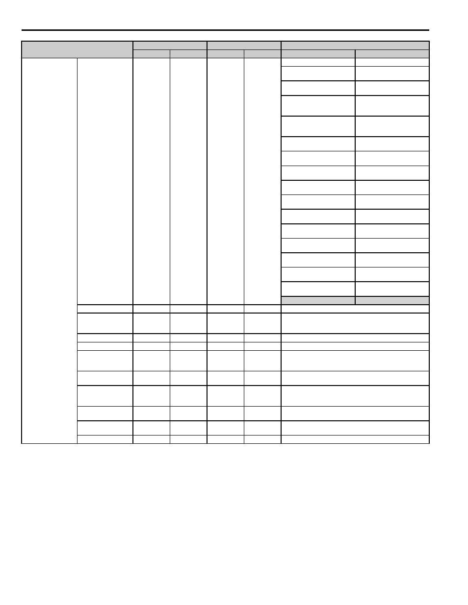
10 Appendix 2 Parameter Cross Reference
44
YASKAWA PL.A1000.01 G5 to A1000 - Product Transition Guide
V/f Characteristic
V/f Pattern Selection
E1-03
F
E1-03
F
E1-03
E1-03
0: 50 Hz spec. (constant torque
characteristics 1)
0: 50 Hz spec. (constant torque
characteristics 1)
1: 60 Hz spec. (constant torque
characteristics 2)
1: 60 Hz spec. (constant torque
characteristics 2)
2: 60 Hz spec. (constant torque
characteristics 3),
voltage saturation at 50 Hz
2: 60 Hz spec. (constant torque
characteristics 3),
voltage saturation at 50 Hz
3: 72 Hz spec. (constant torque
characteristics 4),
voltage saturation at 60 Hz
3: 72 Hz spec. (constant torque
characteristics 4),
voltage saturation at 60 Hz
4: 50 Hz spec.
(derated torque 1)
4: 50 Hz spec.
(derated torque 1)
5: 50 Hz spec. (derated torque
2)
5: 50 Hz spec.
(derated torque 2)
6: 60 Hz spec.
(derated torque 3)
6: 60 Hz spec.
(derated torque 3)
7: 60 Hz spec.
(derated torque 4)
7: 60 Hz spec.
(derated torque 4)
8: 50 Hz spec.
(high starting torque 1)
8: 50 Hz spec.
(high starting torque 1)
9: 50 Hz spec.
(high starting torque 2)
9: 50 Hz spec.
(high starting torque 2)
A: 60 Hz spec.
(high starting torque 3)
A: 60 Hz spec.
(high starting torque 3)
B: 60 Hz spec.
(high starting torque 4)
B: 60 Hz spec.
(high starting torque 4)
C: 90 Hz spec. ,
Voltage Saturation at 60 Hz
C: 90 Hz spec. ,
Voltage Saturation at 60 Hz
D: 120 Hz spec. ,
Voltage saturation at 60 Hz
D: 120 Hz spec. ,
Voltage saturation at 60 Hz
E: 180 Hz spec. ,
Voltage saturation at 60 Hz
E: 180 Hz spec. ,
Voltage saturation at 60 Hz
F: User-Set V/f pattern
F: User-Set V/f pattern
Max Output Frequency
E1-04
60.0 Hz*
E1-04
60.0 Hz*
*Depends on the control mode and the V/F pattern selected.
Max Voltage
E1-05
230.0 V*
E1-05
*
* Depends on the control mode and the V/F pattern selected .
Double values for 400 V class drives. Multiply by 3 for 600 V
class.
Base Frequency
E1-06
60.0 Hz*
E1-06
*
*Depends on the control mode and the V/f pattern selected.
Mid. Output Frequency
E1-07
3.0 Hz*
E1-07
3.0 Hz*
*Depends on the control mode and the V/f pattern selected.
Mid. Output Frequency
Voltage
E1-08
12.6 V*
E1-08
*
*Depends on the control mode and the V/f pattern selected.
Double values for 400 V class drives.
Multiply by 3 for 600 V class.
Minimum Output
Frequency
E1-09
0.5 Hz*
E1-09
*
*Depends on the control mode and the V/f pattern selected.
Minimum Output
Frequency Voltage
E1-10
2.3 V*
E1-10
2.3 V*
*Depends on the control mode and the V/f pattern selected.
Double values for 400 V class drives.
Multiply by 3 for 600 V class.
Mid. Output Frequency
2
E1-11
0.0 Hz
E1-11
0.0 Hz
─
Mid. Output Frequency
Voltage 2
E1-12
0.0 V
E1-12
0.0 V
─
Base Voltage
E1-13
0.0 V
E1-13
0.0 V
─
Parameter Name
G5
A1000
Comments (Gray shading indicates default settings)
No.
Default
No.
Default
G5
A1000