6 main control pcb comparison – Yaskawa GPD515/G5 User Manual
Page 13
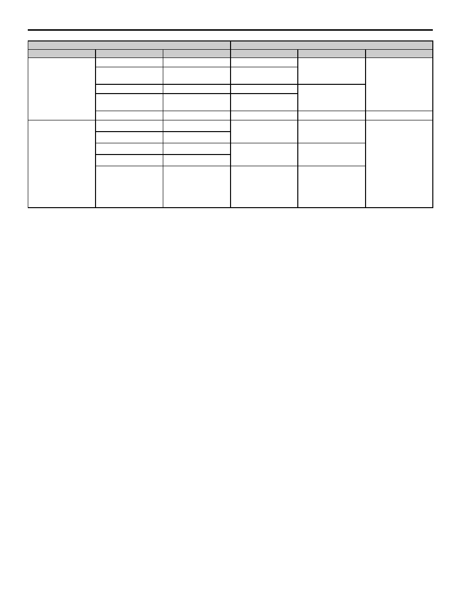
6 Main Control PCB Comparison
YASKAWA PL.A1000.01 G5 to A1000 - Product Transition Guide
13
RS-485/422
—
—
R+
MEMOBUS/Modbus
Communication (RS485/
422)
Max 115.2 kBps
–
—
—
R-
—
—
S+
MEMOBUS/Modbus
Communication (RS485/
422)
Max 115.2 kBps
—
—
S-
—
—
IG
Signal common
–
Safe Diable Inputs
—
—
H1
Safe Disable Input 1
24 Vdc, 8 mA
One or both open: Output
disabled
Both closed: Normal
operation
Internal impedance: 3.3 kΩ
Off time of at least 1 ms
Disconnect the wire jumpers
shorting terminals H1, H2,
and HC to use the Safe
Disable inputs. Set the S5
jumper to select between
sinking, sourcing mode, and
the power supply.
—
—
—
—
H2
Safe Disable Input 2
—
—
—
—
HC
Safe Disable Function
Common
GPD515/G5 Terminal
A1000 Terminal (Designations similar to GPD515/G5)
Type
GPD515/G5 Terminal
Default Functions
A1000 Terminal
Default Function
A1000 Description